
Where to buy crimps for big three upgrade?

Disclaimer: Links on this page pointing to Amazon, eBay and other sites may include affiliate code. If you click them and make a purchase, we may earn a small commission.

Matthew Jeschke

Full Access Member
Joined
Dec 28, 2017
Posts
2,367
Reaction score
1,762
Location
Sahuarita, Arizona
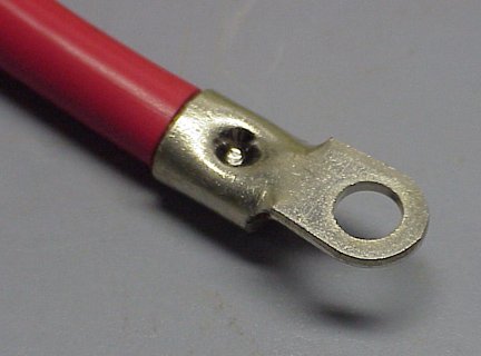
This is probably on the forum somewhere but I cannot find it. I need to buy crimp terminals for big three upgrade. Specifically this:

GROUNDS: Engine block and chassis grounds replaced, need to splice them together and have a single terminal to battery post (side post)

Battery Positive: I think I'll take the alternator post directly to the splice for starter, and relay junction box. Then have the three go to the post. Not exactly my favorite... I'd like to use the Bat+ junction box but think this will work a tad better.

Backstory: Alternator gave out. Quite an adventure, nursed it home at 3500 RPM from deep in mountains. Bought a 240 amp high output alternator. I think it does like 130amps at idle from Tucson Alternator where I live. They sold me a big three kit. I figured the kit would be specific to GMT800. It was not. It's generic and a PITA. I can start truck but cables are TERRIBLY routed and will certainly get caught insomething. I'm trying to route them just as factory did. I don't know why they didn't make a factory replacement setup. It wouldn't have been much more work to do. However, I don't know where to buy the crimp terminals for that large gauge of wire with compatible side post terminals.

Video linked HERE

1689395442289.png

1689395466248.png
 
OP
OP
Matthew Jeschke

Matthew Jeschke

Full Access Member
Joined
Dec 28, 2017
Posts
2,367
Reaction score
1,762
Location
Sahuarita, Arizona
I think I may need to convert to a top post style. I cannot for the life of me find the factory style crimp connectors for several 0 Gauge wires. Most all the tutorials I'm seeing leave quite a lot to be desired with their custom battery / charging cables.
 

Tonyrodz

Resident Resident
Joined
Feb 16, 2012
Posts
33,348
Reaction score
51,845
Location
Central Jersey
I think I may need to convert to a top post style. I cannot for the life of me find the factory style crimp connectors for several 0 Gauge wires. Most all the tutorials I'm seeing leave quite a lot to be desired with their custom battery / charging cables.
Pretty sure @iamdub or @Rocket Man has experience with those. Hopefully they'll chime in.
 
OP
OP
Matthew Jeschke

Matthew Jeschke

Full Access Member
Joined
Dec 28, 2017
Posts
2,367
Reaction score
1,762
Location
Sahuarita, Arizona
Awesome thanks @Tonyrodz

I'm sitting here kind of amazed. It looks as though one person did this Big 3 Upgrade and everybody online copied it then made tutorials off it. I may need to come up with a custom way to do this so it's proper fitment for our trucks. It appears as though people are retrofitting welding terminal crimps and cable for this. Those crimps are great, but they won't accommodate several 0 Gauge wires for a terminal... Converting to side post is an equal headache as you have to get the expensive side post terminals (and adapter lugs) then bolt on all the extra terminals. Additionally, I should upgrade the wire to the under hood junction box as well which seems nobody does or includes in a kit. Studying the factory battery ends / terminal crimps, I can see they are cut from a sheet of metal then folded / pressed over. If I had a CNC plasma cutter and some dies I could probably do that but doesn't appear anybody sells the factory style side mount cable terminals.
 

Scottydoggs

Full Access Member
Joined
Dec 16, 2017
Posts
2,886
Reaction score
4,527
Location
NJ
when i need to put a eyelet on a cable i used solder, heat and fill the eyelet up with solder, flux the bare wire end and push it into the eyelet. how ive done all of em for years now, like my dual battery and snow plow cables. then a few busted off ends over the years on many cars and trucks. you will also need to get the side post extenders so you got the room to add the new eyelets to the battery. best type ive found is the one that replaces the fatory bolt, then has a stud and a nut to put the new cables.

like these. its nice to get em tight and never worry about the little pos bolt stripping out.

006.JPG
 
OP
OP
Matthew Jeschke

Matthew Jeschke

Full Access Member
Joined
Dec 28, 2017
Posts
2,367
Reaction score
1,762
Location
Sahuarita, Arizona
Gotchya, I see the post extenders. Those will work for time being. I kind of hate all the extra hoopla on the cables. I like a nice clean crimped setup.

You've not had any issues with heating at the solder joints? From what I understand current travels on surface of conductor, is why battery cables are never soldered from factory from what I understand.
 

wjburken

Elite Member
Supporting Member
Joined
Dec 26, 2017
Posts
10,315
Reaction score
29,545
Location
Eastern Iowa
Gotchya, I see the post extenders. Those will work for time being. I kind of hate all the extra hoopla on the cables. I like a nice clean crimped setup.

You've not had any issues with heating at the solder joints? From what I understand current travels on surface of conductor, is why battery cables are never soldered from factory from what I understand.
A good solder joint shouldn’t have any issues.
 
OP
OP
Matthew Jeschke

Matthew Jeschke

Full Access Member
Joined
Dec 28, 2017
Posts
2,367
Reaction score
1,762
Location
Sahuarita, Arizona
It just dawned on me, I'm going about this the wrong way.

My buddy had a Volkswagen Beatle. Basket of worms that car, but aside from that. I noticed it had a terminal block. All the systems connecting to Battery+ under the hood were routed through a terminal block, kind of like that red box between the alternator and battery only bigger.

I think I should just get a sheet of copper and run some bolts through it to connect up the grounds. Then something similar, but needs insulated for the battery positive.

Anybody seen a slick custom setup for that before?
 

Alex_M

Full Access Member
Joined
Sep 27, 2021
Posts
380
Reaction score
687
Doing a distribution block for grounds isn't necessary. The entire chassis is a ground, so as long as your grounds between frame/body/engine are solid then you do not need to run grounds all the way back to the battery. If you want to anyway - aluminum is perfectly adequate, no need to drop the coin on copper. Just grab a piece of like 1/2" thick aluminum bar and you can tap it to accept 3/8 bolts.

Welding terminals are what I use.

You can also get an isolated distribution block for your positives so that they don't have to all come back to your battery. Personally though, I switch over to top post batteries and use marine terminals in all my vehicles. Usually only have 2 or 3 cables coming off the battery directly - factory cable for the fuse box, alternator if upgraded, and starter if upgraded. Sometimes I'll have a winch hooked up or a stereo amp, but it rarely totals more than three cables for me personally.
 
Last edited:

Joseph Garcia

Elite Member
Supporting Member
Joined
Aug 2, 2018
Posts
10,569
Reaction score
15,362
This is probably on the forum somewhere but I cannot find it. I need to buy crimp terminals for big three upgrade. Specifically this:

GROUNDS: Engine block and chassis grounds replaced, need to splice them together and have a single terminal to battery post (side post)

Battery Positive: I think I'll take the alternator post directly to the splice for starter, and relay junction box. Then have the three go to the post. Not exactly my favorite... I'd like to use the Bat+ junction box but think this will work a tad better.

Backstory: Alternator gave out. Quite an adventure, nursed it home at 3500 RPM from deep in mountains. Bought a 240 amp high output alternator. I think it does like 130amps at idle from Tucson Alternator where I live. They sold me a big three kit. I figured the kit would be specific to GMT800. It was not. It's generic and a PITA. I can start truck but cables are TERRIBLY routed and will certainly get caught insomething. I'm trying to route them just as factory did. I don't know why they didn't make a factory replacement setup. It wouldn't have been much more work to do. However, I don't know where to buy the crimp terminals for that large gauge of wire with compatible side post terminals.

Video linked HERE

View attachment 404006
View attachment 404007
Go to a good car audio shop that does installations, and I'm sure that they will have what you need.
 

iamdub

Full Access Member
Joined
Apr 23, 2016
Posts
20,821
Reaction score
45,016
Location
Li'l Weezyana
It just dawned on me, I'm going about this the wrong way.

My buddy had a Volkswagen Beatle. Basket of worms that car, but aside from that. I noticed it had a terminal block. All the systems connecting to Battery+ under the hood were routed through a terminal block, kind of like that red box between the alternator and battery only bigger.

I think I should just get a sheet of copper and run some bolts through it to connect up the grounds. Then something similar, but needs insulated for the battery positive.

Anybody seen a slick custom setup for that before?

After this, I was all like:

1s3zsg.jpg


Doing a distribution block for grounds isn't necessary. The entire chassis is a ground, so as long as your grounds between frame/body/engine are solid then you do not need to run grounds all the way back to the battery. If you want to anyway - aluminum is perfectly adequate, no need to drop the coin on copper. Just grab a piece of like 1/2" thick aluminum bar and you can tap it to accept 3/8 bolts.

Welding terminals are what I use.

You can also get an isolated distribution block for your positives so that they don't have to all come back to your battery. Personally though, I switch over to top post batteries and use marine terminals in all my vehicles. Usually only have 2 or 3 cables coming off the battery directly - factory cable for the fuse box, alternator if upgraded, and starter if upgraded. Sometimes I'll have a winch hooked up or a stereo amp, but it rarely totals more than three cables for me personally.

Then I was all like:

69ex37.png


@Matthew Jeschke, as @Alex_M said, a bus bar or distribution block isn't necessary for the ground. The entire frame functions as this. You can convert your side post battery have studs with two different styles- the ones @Scottydoggs showed or these:

892e-c76381f30140.29f14697b78f3b686970bdb5ae802350.jpg


I got marine lugs from Amazon. They're tinned copper. Soldered them on the way that @Scottydoggs outlined, then crimped with a handheld hydraulic crimper. I also used marine battery terminals with regular nuts instead of the wing nuts:

81txZm+8HcL._AC_SL1500_.jpg


Run one large cable from the battery negative to the frame and one large cable from the frame to the engine. You can have the engine ground at the same point as the battery ground of anywhere else that's convenient. The upgraded charge cable can be one from the battery to the access point in that red plastic box, then the same size from that box to the alternator. Or, leave the factory stuff as-is and just run one large cable from the alternator to the battery positive.


Here's my shizz:


If you have an RVC sensor and if your new alternator is compatible, run your ground through the sensor. I re-did my stuff later to have the one ground cable and had it passing through the sensor:


In the pics in that link, you can see I have three cables on the battery. The ground, the charge cable from the alternator and the upgraded cable to the starter.
 
OP
OP
Matthew Jeschke

Matthew Jeschke

Full Access Member
Joined
Dec 28, 2017
Posts
2,367
Reaction score
1,762
Location
Sahuarita, Arizona
Dang I get a sense of what you did from your photo but cannot exactly see. You grounded where the red BAT box was before. Would be easier that reaching down to the side of the block. My mind wonders why they made the chassis ground in such a precarious place (front drive body mount / core support mount on frame).

I got it rigged up to work right now. Waiting on crimp tool in mail. I'm going to shorten the alternator cable they sent me, it's a good foot too long. Then I just rigged with battery post adapters kind of like you showed.
 

iamdub

Full Access Member
Joined
Apr 23, 2016
Posts
20,821
Reaction score
45,016
Location
Li'l Weezyana
Dang I get a sense of what you did from your photo but cannot exactly see. You grounded where the red BAT box was before. Would be easier that reaching down to the side of the block. My mind wonders why they made the chassis ground in such a precarious place (front drive body mount / core support mount on frame).

I got it rigged up to work right now. Waiting on crimp tool in mail. I'm going to shorten the alternator cable they sent me, it's a good foot too long. Then I just rigged with battery post adapters kind of like you showed.

I should've specified, but thought the pics would show. Mine's an '08 (GMT900/NNBS), which doesn't have that red BAT+ connection and the battery is in the rear passenger corner of the engine bay. My point was showing the necessary circuits and terminations, not specifically the routing and locations on your model.

Grounds should be as short as possible. There's a bolt in the block for the power steering pump bracket and a strut mount stud and nut is very near that. Yours doesn't have struts but the idea is to find something on the frame that's near a threaded boss or existing bolt on the engine block. A flat piece of the frame (or a cross member) that's accessible to both sides would be great since you could drill a hole and bolt the cable to it. I haven't memorized the GMT800 frame to this degree or I'd have a less vague answer. The universal kits are made a bit long with the intention for you to trim as needed.
 

adriver

Full Access Member
Joined
Aug 18, 2018
Posts
787
Reaction score
477
Do not splice your two grounds together. Run two separate cables. One from batt - to chassis, and the other from batt - to engine block, (alternator mounting bolt).

Do not splice to the starter or relay junction box. Your alternator goes to batt +. (that's the big 3).

The terminals are just "cable lugs" or "copper lugs". Find where you want to mount them and you can get the bolt hole size, and order them for your wire size. You can find them on ebay, amazon, many audio car dealers sell them. I think Home Depot sells them. A big name is Selterm. No reason you can't find those.

The lugs are the same for top or side mounted posts. You don't need a new battery, you need "extended battery terminals".

DO NOT try to fit several larger 1/0 size wires into one lug/splice them together. With the extended terminals, you just stack the lugs.

"CNC plasma cutter, sheet of metal folded, and pressed over", holy shit you are making this complicated. No. Just make your big 3 cables, (3) of them, all 1/0 with lugs on the end, and stack the two negative cables on the extended terminal.

The terminal blocks are already out there, I promise you, you don't need to make them yourself. You can search amazon for ideas. Start here, then look at similar items to find your style:

Not sure what grounds you are talking about using a distribution block to, but ground is chassis, not the battery. If battery neg was ground, then you could disconnect the neg cables and it would start, it won't.

Not sure if you need thoughts on your stereo, but this thread seemed like it was just to tackle the big 3.

Don't solder and crimp your connectors. That's unnecessary, and a hydraulic crimper is more likely to damage the solder.

Your factory alternator cable was a "Fused link". The cable was specifically sized, so that if the alternator overcharges, the cable would internally melt and the protective sheath would not. The sheath would stay intact so not to risk a hot wire coming in contact with anything in the engine bay, creating a circuit and fusing to create a circuit that would melt your vehicle down. IT IS RARE, but now you've added a higher amperage alternator. MOST PEOPLE add a fuse inline to protect from the alternator going haywire.
 

steve45

Full Access Member
Joined
Sep 20, 2013
Posts
130
Reaction score
98
You can get large cable ends at an electrical supply house, auto parts stores, etc.

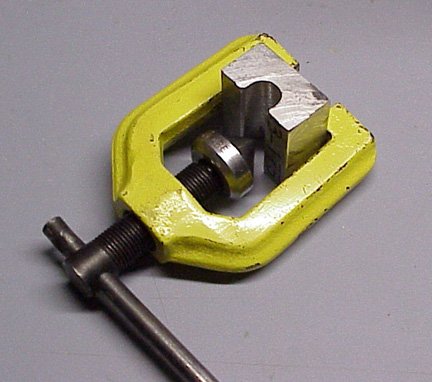
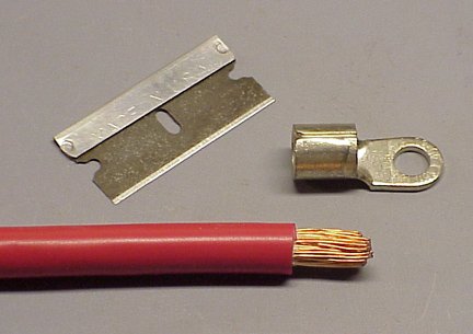
Here's how I attach them when I make a battery cable using a flaring tool and a block of aluminum. I drilled a hole in the aluminum to fit the diameter of the terminal, then sawed it in half.
 

Attachments

  • Cable Crimper 2.JPG
    Cable Crimper 2.JPG
    68.3 KB · Views: 32
  • Battery Cable #1.JPG
    Battery Cable #1.JPG
    72.1 KB · Views: 29
  • Battery Cable #2.JPG
    Battery Cable #2.JPG
    66.1 KB · Views: 35

Forum statistics

Threads
138,123
Posts
1,999,801
Members
103,047
Latest member
X-ray Nerd

Latest posts

Back
Top