OP
OP
- Joined
- May 15, 2021
- Posts
- 546
- Reaction score
- 1,348
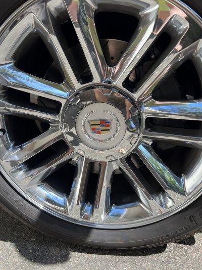
I lived with the spacing issue by installing 15mm hubcentric spacers and longer lug studs. I have been daily driving my Escalade since then with no issues.Hey Seth, Hope you've been able to clear up the spacing issue. I'm curious to know how your project is coming along as i'm getting ready to start my upgrade this weekend. Hopefully I don't have the spacing issues as i'm running aftermarket 24 inch rims.
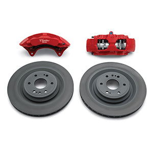
It was not necessarily the diameter of the rim, but the offset of the rim. The back of my wheel spokes hit the outside of the calipers.
Good Luck!
NOTE: this is with the Brembos spec'd out for the 2022 Tahoe PPV. If you use the Brembos listed a couple of posts above, you probably won't have fitment issues.