
DIY Alignment 07 Tahoe 4WD

Disclaimer: Links on this page pointing to Amazon, eBay and other sites may include affiliate code. If you click them and make a purchase, we may earn a small commission.

89Suburban

Bull in the china shop
Space X Supporting Member
Joined
Jan 10, 2013
Posts
18,031
Reaction score
51,351
Location
SE PA
Moving all my R&D into this thread for my reference so its not skewed all over the GMT900 thread and anyone else that wants to follow along including the peanut gallery.

I have been having issues getting the local shops to do an alignment on my truck because it is "modified" from stock which is fk'n bullsh*t. Compared to all the other highly modified hunks of shit I see running around here. I do have one place left I can bust his balls and he will do it or let me rent the rack to do it myself with his mentoring. I am keeping that in reserve and decided to learn what I can on my own just becuz. :flipthebird:


And it's a new challenge and education which I enjoy and have something to feed my OCD and mental mechanical anguish. Or make it worse.


Anyway so I did basically 2" drop front and rear. Front was the flipped struts to under the arm mod with the grade 9 hardware. This absolutely throws everything out of whack. So I have just been eyeballing things and adjusting, road testing, trial and error process if you will.

So I just eyeballed the camber compared to the rear wheels and got close to where I thought it should be. Def a ton of pos camber had to be adjusted to get the tire close to square to the road. I still have a few degrees of adjustment left with the factory bolts if I need it. Hoping I will not be needing to go with the offset bolts.

I came across this very nifty little tool on Amazon, so far it is very fun tool to play with. And for 16 bucks, why not? The big thing about this tool is to get measurements off the rotor before replacing suspension parts so you can match the adjustment of the new ones close enough to get by until you can get an alignment scheduled. This tool feels good in your hands for a 16 dollar tool. (Mounted to the 12 oz beer crusher for size reference. Another $15 dollar tool that I love.)


39839bcd-4fef-4696-9065-3b81814d3a23-jpeg.jpg
 
Last edited:
OP
OP
89Suburban

89Suburban

Bull in the china shop
Space X Supporting Member
Joined
Jan 10, 2013
Posts
18,031
Reaction score
51,351
Location
SE PA
One thing I can say for sure is I spent a few weeks trying to dial the toe in by eye. That is a nightmare. I never got anywhere close. It would always be pulling one way or the other or steering wheel would be off center. You don't realize how much those adjusters on the tie rods move that wheel. Recently I got what I thought was real close. There is no way to get a tape measurement across the chassis onto the tire treads for this.

I was looking at some tie rod adjustment plate setups online. I was thinking of just making my own out of some strong ass laminated birch plywood we have at work. And I could notch the bottoms out to go over the tire bulge at the bottom. Something I don't see how the tie rod plates address unless you buy the ones with the wheel pegs that sit against the rim. That just seems to chinsey to me.

So I decided to use 4 washer jugs with string lines. Squared them up to the rear wheels and used that to adjust the toe. It worked pretty good! Real pain in the ballz to get the rear lined up square but once it is, you are dialed in! Before you set the lines up you can turn the tires lock to lock to knock the lock nuts loose off the tie rods (15/16" wrench).

Then set the steering wheel straight. You can then setup your lines and adjust your toe with a tape measure to the string line. You can just make the reach into the wheel well with a 5/8" wrench to adjust the tie rods. I just set a generic setting to 1/16" toe in on both sides. Remember the rear of the wheel moves out as well. So if you are off a 1/4" you only need to move half that. It does mess with your mind.


92c4d6d1-7e7c-4a94-9187-7fb8e17d6aeb-jpeg.jpg
 
Last edited:
OP
OP
89Suburban

89Suburban

Bull in the china shop
Space X Supporting Member
Joined
Jan 10, 2013
Posts
18,031
Reaction score
51,351
Location
SE PA
One thing I kept doing is going back to check the steering wheel was staying straight during this process. It does not lock into place like the older trucks. I plan on ordering this little guy for the final adjustments once I get the camber stuff sorted out.


51kBQpw3nQL._AC_SX679_.jpg
 
OP
OP
89Suburban

89Suburban

Bull in the china shop
Space X Supporting Member
Joined
Jan 10, 2013
Posts
18,031
Reaction score
51,351
Location
SE PA
Comparison of both front readings, beginning with driver's side. Pass side is about half a degree off the driver's side. -1*+ compared to -1 1/2*+. After the toe in adjustment with the string line I still have a very slight pull to the right, especially on a road crown. But the wheel is straight and true on flat crown sections.


366788d8-1090-4df4-8365-b43ec3e032d8-jpeg.jpg
0a433022-bfd7-4528-83e0-e8df5623a126-jpeg.jpg
 
OP
OP
89Suburban

89Suburban

Bull in the china shop
Space X Supporting Member
Joined
Jan 10, 2013
Posts
18,031
Reaction score
51,351
Location
SE PA
I know that I have not mentioned castor adjustments yet and that is a whole other bucket of bolts. And have no idea how I am going to tackle that other than trying to get the spacing difference on the locating pins adjustments on the alignment keys close as I can to the factory cam locks pictured here. From that my pea brain can make out there seems to be just a slight more factory castor on the passenger (L) side than the driver's side (R). So trying to keep that in sync with an actual dialed in camber setting close as possible.


1cd041eb-6d09-4e81-b7f5-0228f0a36886-jpeg.jpg
 
OP
OP
89Suburban

89Suburban

Bull in the china shop
Space X Supporting Member
Joined
Jan 10, 2013
Posts
18,031
Reaction score
51,351
Location
SE PA
This would be the more likely installed position looking from the front of the truck:


IMG_4978.jpg


Pin holes aligned:


IMG_4979.jpg
 
OP
OP
89Suburban

89Suburban

Bull in the china shop
Space X Supporting Member
Joined
Jan 10, 2013
Posts
18,031
Reaction score
51,351
Location
SE PA
Now I am trying to track down alignment specs. I found this generic one on Auto Zone website. If I go by this the cambers are damn close. But it says for 4WD it's an actual toe out of .20 degrees??? I am assuming that is on each side, not overall?


spec1.jpg


Using this calculator that comes out to a .11" out? ....


Which according to this is 7/64", just a hair under 1/8" toe out?


IMG_4980.jpg
 

iamdub

Full Access Member
Joined
Apr 23, 2016
Posts
20,821
Reaction score
45,013
Location
Li'l Weezyana
My man!

I dropped mine with spindles and struts and replaced all the arms (new bushings and BJs) at the same time. I kept the original alignment settings even after I elongated the slots to use the Belltech cams so I'd have a solid baseline. I used two large ("12 Ton") HF jack stands as my anchors for the string and just did one side at a time. Squared the front off the rear using a stainless metric ruler, aligning the ruler mark with the center of the string for as much precision as possible. For camber, I used a digital angle finder (https://www.amazon.com/Klein-Tools-935DAG-Electronic-Measures/dp/B07ZWW3BW5). I cut a piece of angle iron to span the wheel lips, covered it with painter's tape so it wouldn't scratch the wheel and stuck the angle finder to the center (magnetic). I didn't have a solid way to measure and set the caster, so I erred for more positive caster. I actually have too much, but it's mostly harmless. I hade all four wheels on matching stacks consisting of a concrete block and 2x8s. I put cheap cookie sheets under the front wheels to make turning the wheels by hand easy. I don't recall the toe-in I set, but I wanna say it was 1/16". I don't recall if that was per side or total (1/32" per side). I brought two large crescent wrenches with me on the first test drive to stop at the park and fine-tune the toe to center the steering wheel. I'd adjust each side as evenly as possible, taking from one and giving that same amount to the other, to maintain the toe but "push" the steering wheel whichever way until it was level/centered.

All this was intended to get it within a safe range to drive to an alignment shop. ~25K miles later, I've yet to touch it. Tires wear evenly, it doesn't pull, steering wheel is straight and the only odd feeling is when backing and turning due to the excessive positive caster making it act like negative caster would when rolling forward. I'm not finished with the suspension stuff so I'll adjust out some of that caster then.
 
OP
OP
89Suburban

89Suburban

Bull in the china shop
Space X Supporting Member
Joined
Jan 10, 2013
Posts
18,031
Reaction score
51,351
Location
SE PA
HUGE difference of readings on a super flat troweled floor. Dang.


Going R/R to R/F listening to thing that should not be:


6B3B2E0E-0534-4268-B3EC-594BD6FC1CDB.jpeg
C6AE7E9D-8F7E-470D-BAB9-BBC2A653B834.jpeg
67D2DC3F-ACB7-4FFE-9212-30A2700DFC6D.png
 
Joined
Apr 11, 2018
Posts
7,124
Reaction score
14,376
Location
St. Louis
So how hard is it to adjust the camber? I know the upper control arm bolts have those curved washer thingys and I'm guessing the bushing is off center. What do you actually do, loosen the bolts and use a prybar or something to move the control arm at the bushing in/out/up/down/etc then tighten back up?
 
OP
OP
89Suburban

89Suburban

Bull in the china shop
Space X Supporting Member
Joined
Jan 10, 2013
Posts
18,031
Reaction score
51,351
Location
SE PA
So how hard is it to adjust the camber? I know the upper control arm bolts have those curved washer thingys and I'm guessing the bushing is off center. What do you actually do, loosen the bolts and use a prybar or something to move the control arm at the bushing in/out/up/down/etc then tighten back up?
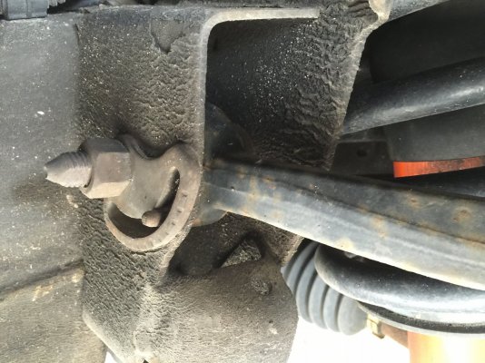
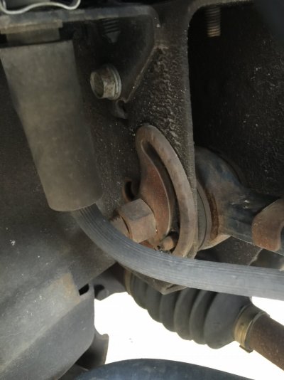
The 2 mounting bolts are straight, the bolt holes in the frame are slotted. There are small pins that stick out of the frame that the slot of the 4 washer keys slide on. Depending which way you turn the bolt head pulls the a-arm in or out. You adjust front to back for the castor and in or out for camber.
 

Attachments

  • IMG_0859.JPG
    IMG_0859.JPG
    356.4 KB · Views: 44
  • IMG_0860.JPG
    IMG_0860.JPG
    205.8 KB · Views: 34

Forum statistics

Threads
138,035
Posts
1,997,532
Members
102,973
Latest member
CRN_25
Back
Top