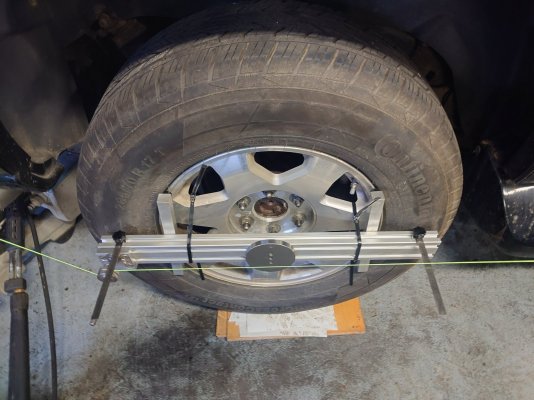
Well, today I was finally able to go to my wheel alignment after my axle work.
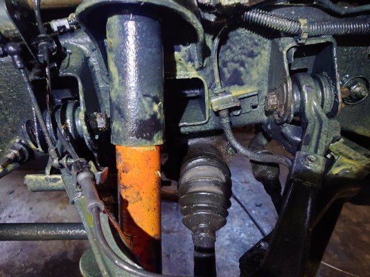
First I had to find out how it works with the GMT800. I had already discovered the necessary adjustment screws on the upper control arm, but didn't want to loosen them until now, because I wanted to measure the initial situation.
Today I measured caster and camber and found that they were not correct or outside of the tolerance range and I loosened the screws.
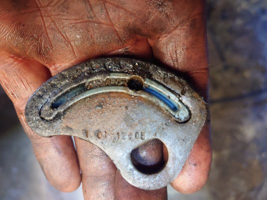
I then found out that the rear ones on both sides are so tight that they cannot be turned. I also found a strange piece of plastic in the setting plates. There was a big question mark at first because this plastic part dictated the setting, so to speak.
But youtube is your friend and that's how I found out that these are retainers that come from the production of the vehicle, i.e. the factory setting, so to speak.
This tells me that in the 200,000 km that my car has driven, the axle has not even been adjusted. Anyway, it was a big job to loosen the rear screws. Hammer, oil, heat and a lot of patience brought the desired result.
After that, with my wife turning the steering wheel, I was able to get the camber and caster to the correct values.
The toe will come tomorrow. I'm curious to see how the car drives.
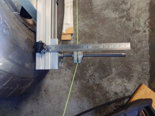
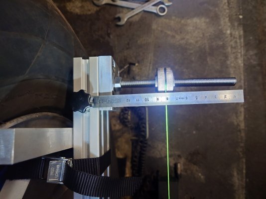
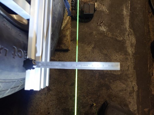
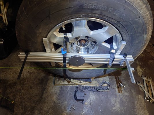
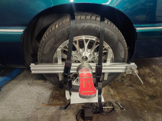
I'll post pictures of my modified system tomorrow.
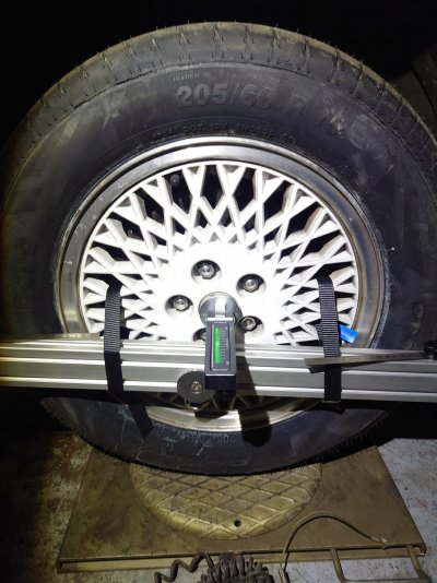
Here is just a picture of these retainers and the upper axle adjustment screws