New user intro

Disclaimer: Links on this page pointing to Amazon, eBay and other sites may include affiliate code. If you click them and make a purchase, we may earn a small commission.

Sparksalot

Elite Member
Joined
Sep 20, 2020
Posts
6,775
Reaction score
20,587
Location
Bastrop County, Texas
Ok. I am taking a break from trying to figure this out and will humbly ask for some help from the knowledgeable folks here. Here are the wire bundles currently in question:

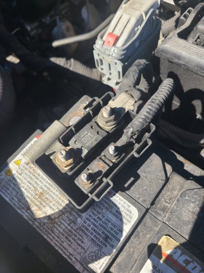
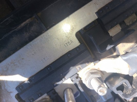
The first picture has no tag or markings but has these three separate bundles with these connectors inside: The black connector has a red and black wire (along with some others) that is hot when the ignition is off. The gray connector with the blue at the bottom has ONLY a red and black wire that is ONLY hot when the ignition is on (not running.) The third connector looks like some sort of phone charger plug similar to an older Motorola plug.

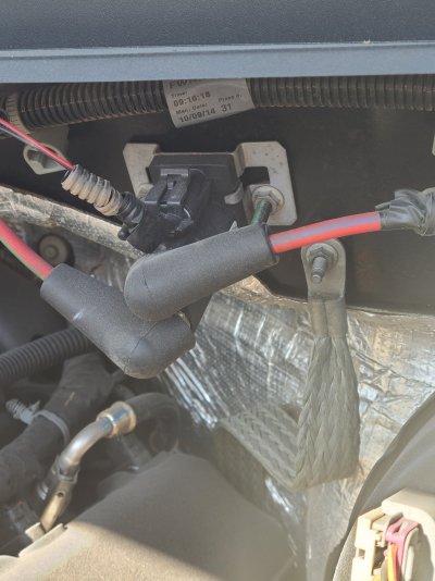
The second picture has a tag that is torn in the middle but the barcode scans out to "6G4". It has a single wire that loops around and connects back with the bundle. No clue on that one.

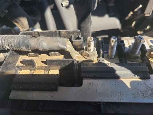
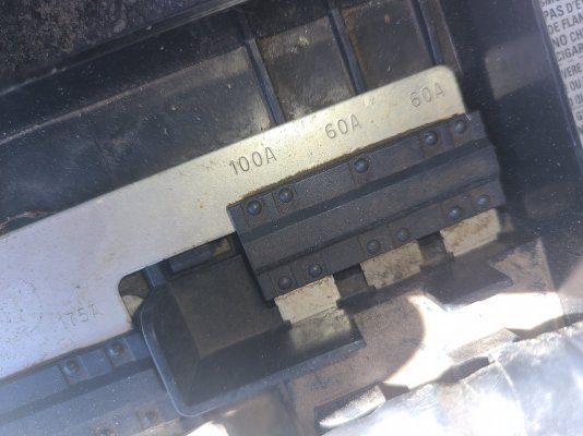
The third and fourth picture s has a tag showing "5W49C1" (photo 3). It has two heavy gauge wires (black and red) but there is no power there regardless of the key position. It also has several smaller wires in the bundle shown in photo 4.

I'll add a couple more bundles after dinner. Anyone with insight is welcome to chime in. ;-)
First pic is a head scratcher. The second one with light brown is your horn ring. That's the one to go looking for if your horn didn't work after decommissioning.

Have you looked at the GM Upfitter Guide for the wiring diagrams? There is a guide specifically for the PPV. It may answer a number of your questions now, and in the future.
 
OP
OP
Lanman61

Lanman61

TYF Newbie
Joined
Mar 13, 2023
Posts
27
Reaction score
72
Location
Phoenix, AZ
First pic is a head scratcher. The second one with light brown is your horn ring. That's the one to go looking for if your horn didn't work after decommissioning.

Have you looked at the GM Upfitter Guide for the wiring diagrams? There is a guide specifically for the PPV. It may answer a number of your questions now, and in the future.
I have both the 2015 Tahoe 2WD Police Package 9C1 guide pgs 19-31 (several easier to read wiring diagrams) and the Special Equipment Options Section 15-1 through 15-17 but not an expert at reading the diagrams.

You have any ideas as to the 3rd and 4th photos? They come out from under the floor plate that the Troy Console bolts to. I suspect they are some of the main ones I need but since the heavy gauge qires have no juice regardless of key position, I have no idea what the issue is as to why not.
 

89Suburban

Bull in the china shop
Space X Supporting Member
Joined
Jan 10, 2013
Posts
17,814
Reaction score
50,748
Location
SE PA
First pic is a head scratcher. The second one with light brown is your horn ring. That's the one to go looking for if your horn didn't work after decommissioning.

Have you looked at the GM Upfitter Guide for the wiring diagrams? There is a guide specifically for the PPV. It may answer a number of your questions now, and in the future.

The first pic the one in the middle looks like a USB-B mini.
 

Sparksalot

Elite Member
Joined
Sep 20, 2020
Posts
6,775
Reaction score
20,587
Location
Bastrop County, Texas
I have both the 2015 Tahoe 2WD Police Package 9C1 guide pgs 19-31 (several easier to read wiring diagrams) and the Special Equipment Options Section 15-1 through 15-17 but not an expert at reading the diagrams.

You have any ideas as to the 3rd and 4th photos? They come out from under the floor plate that the Troy Console bolts to. I suspect they are some of the main ones I need but since the heavy gauge qires have no juice regardless of key position, I have no idea what the issue is as to why not.
I’m guessing you also don’t have power at the two 50 amp feeds under the interior trim at the left rear wheel well. On thecopcar the main feed to the cabin had been cut. The mega fuse was also missing at the battery terminal.
 
OP
OP
Lanman61

Lanman61

TYF Newbie
Joined
Mar 13, 2023
Posts
27
Reaction score
72
Location
Phoenix, AZ
You would be 100% correct! I've put an ohm meter on the two large fuses on the + terminal of the auxiliary battery (Picture 1) and they both test ok. All wiring that you showed in your previous pictures looks ok. Where would the best place to start looking for that break in the main harness? I did notice that the Ignition Controlled Charging Relay is still installed and hooked up (Picture 2).

I also located this in the box mounted above the main battery. Is this (Pictures 3-5) where I need to start looking?
 

Attachments

  • 2023-03-29 09.30.23.jpg
    2023-03-29 09.30.23.jpg
    392 KB · Views: 35
  • 2023-03-29 09.30.40.jpg
    2023-03-29 09.30.40.jpg
    283.4 KB · Views: 34
  • 2023-03-29 09.34.46.jpg
    2023-03-29 09.34.46.jpg
    277.9 KB · Views: 38
  • 2023-03-29 09.35.10.jpg
    2023-03-29 09.35.10.jpg
    327.7 KB · Views: 35
  • 2023-03-29 09.35.19.jpg
    2023-03-29 09.35.19.jpg
    287.6 KB · Views: 31

Sparksalot

Elite Member
Joined
Sep 20, 2020
Posts
6,775
Reaction score
20,587
Location
Bastrop County, Texas
You would be 100% correct! I've put an ohm meter on the two large fuses on the + terminal of the auxiliary battery (Picture 1) and they both test ok. All wiring that you showed in your previous pictures looks ok. Where would the best place to start looking for that break in the main harness? I did notice that the Ignition Controlled Charging Relay is still installed and hooked up (Picture 2).

I also located this in the box mounted above the main battery. Is this (Pictures 3-5) where I need to start looking?
Are you sure the relay is functioning? Passing current?
 

Doubeleive

Wes
Supporting Member
Joined
Nov 7, 2017
Posts
30,500
Reaction score
47,889
Location
Stockton, Ca.
You would be 100% correct! I've put an ohm meter on the two large fuses on the + terminal of the auxiliary battery (Picture 1) and they both test ok. All wiring that you showed in your previous pictures looks ok. Where would the best place to start looking for that break in the main harness? I did notice that the Ignition Controlled Charging Relay is still installed and hooked up (Picture 2).

I also located this in the box mounted above the main battery. Is this (Pictures 3-5) where I need to start looking?
aside from the 2nd pic those are all just fuses, looks like most have no connection a couple them are spares for whatever you want to add.
take note that if you happen to "blow" one of those "fuse" the entire assembly has to be replaced for the 1 fuse to work again as it is all one piece and runs about $100-120
I have done it already when I installed a bad amp and the amp smoked and blew the fuse with it.
the piece in the 2nd pic is the battery isolator for battery #2
 
OP
OP
Lanman61

Lanman61

TYF Newbie
Joined
Mar 13, 2023
Posts
27
Reaction score
72
Location
Phoenix, AZ
@Lanman61 i had this bookmarked as an idea, but I decided to plastidip the chrome caps on thecopcar.
I saw that on your acquisition timeline posts. ;-) They seem to be pretty pricey. I would do the same as you but not seeing the same thing in chrome. The link you sent says it doesn't fit my 2015 but a chrome one (https://www.gmpartsdirect.com/oem-p...0YWhvZSZ5PTIwMTUmdD1wcHYmZT01LTNsLXY4LWZsZXg=) will. Nothing like the ones that are on it now. May check out some junk yards around town and see what I can scare up. if I can't get any new. Even RockAuto doesn't even show these but they hace the fasteners that hold them on. ;-)
 

Sparksalot

Elite Member
Joined
Sep 20, 2020
Posts
6,775
Reaction score
20,587
Location
Bastrop County, Texas
I saw that on your acquisition timeline posts. ;-) They seem to be pretty pricey. I would do the same as you but not seeing the same thing in chrome. The link you sent says it doesn't fit my 2015 but a chrome one (https://www.gmpartsdirect.com/oem-parts/gm-wheel-center-cap-brushed-aluminum-bowtie-logo-qty-of-1-not-a-set-of-4-19301595?c=YT1jaGV2cm9sZXQmbz10YWhvZSZ5PTIwMTUmdD1wcHYmZT01LTNsLXY4LWZsZXg=) will. Nothing like the ones that are on it now. May check out some junk yards around town and see what I can scare up. if I can't get any new. Even RockAuto doesn't even show these but they hace the fasteners that hold them on. ;-)
Everyone is proud of them, new or used. I found the chrome ones are typically $100 each.
 
OP
OP
Lanman61

Lanman61

TYF Newbie
Joined
Mar 13, 2023
Posts
27
Reaction score
72
Location
Phoenix, AZ
2 questions:

1) If I was to just run a new connection from the rear electrical panel to the center console area, what would be the minimum wire size, fuse protection and routing (easiest, least amount of tear-apart needed)

2) If I was to just run a new connection from the center console area to the auxiliary battery area, what would be the minimum wire size, fuse protection and routing (easiest, least amount of tear-apart needed)

Getting tired of trying to chase down what is already there and what they all do. I'm not an expert at reading the wiring diagrams and none of them really show WHERE they are routed so the time it is taking is getting me down.

On another note, I found if I run a hot wire to one of the green wires (not stripped) in the harness marked 6J3, I can have the headlight/taillight flashers working.

Is this correct or should I be looking for another wire to run juice to?
 
Last edited:
OP
OP
Lanman61

Lanman61

TYF Newbie
Joined
Mar 13, 2023
Posts
27
Reaction score
72
Location
Phoenix, AZ
Progress update: Slowly but surely I am getting things going. I've gotten all LED flashers working on the front. Debating with myself if I should add two more to the push bar. Opinions welcome. Also, updated the taillights & backup lights to LED bulbs. Had to use load equalizers for the brake lights/turn signals but I expected that. Got the lightbar working but I have another bar that I think has better patterns and, frankly looks better. Debating on whether to change it or not. Also, all LED flashers on the back end work and are wired together. No power to them so I need to hunt down the wire that supplies power back there. Also, I need to wire in the two (one on each side) on the sides to the mix.
 

Sparksalot

Elite Member
Joined
Sep 20, 2020
Posts
6,775
Reaction score
20,587
Location
Bastrop County, Texas
Progress update: Slowly but surely I am getting things going. I've gotten all LED flashers working on the front. Debating with myself if I should add two more to the push bar. Opinions welcome. Also, updated the taillights & backup lights to LED bulbs. Had to use load equalizers for the brake lights/turn signals but I expected that. Got the lightbar working but I have another bar that I think has better patterns and, frankly looks better. Debating on whether to change it or not. Also, all LED flashers on the back end work and are wired together. No power to them so I need to hunt down the wire that supplies power back there. Also, I need to wire in the two (one on each side) on the sides to the mix.
Definitely would look good with a pair of strobes on the pushbar.

 
OP
OP
Lanman61

Lanman61

TYF Newbie
Joined
Mar 13, 2023
Posts
27
Reaction score
72
Location
Phoenix, AZ
Definitely would look good with a pair of strobes on the pushbar.

I agree that there is something missing from the front. I decided against the strobes like I already have and went with something different. I'll post more when they arrive.

On another note, since my Troy console went wherever the mechanic that was modifying it went (and didn't tell me where that was) I am hoping to work something out to pick up one that was taken out of a PPV. Waiting on some photos to check condition before making the drive from Phoenix to Austin to get it.
 

Forum statistics

Threads
137,686
Posts
1,989,603
Members
102,687
Latest member
JohanZ
Back
Top