After I did that test, I checked the bulb sockets and for both lights, with high resistance to ground at approx .7 M ohms, the lightbulb will illuminate with the doors open and the POS+ socket to ground reads 12V. The bulb will not light up with the button pressed which provides the same resistance to ground but I'm only getting 11V at the POS+ bulb terminal. One volt less and the bulb does not illuminate.

You are using an out of date browser. It may not display this or other websites correctly.
You should upgrade or use an alternative browser.
You should upgrade or use an alternative browser.
Instrument cluster lights turn off when map light is turned on
- Thread starter dkad260
- Start date
Disclaimer: Links on this page pointing to Amazon, eBay and other sites may include affiliate code. If you click them and make a purchase, we may earn a small commission.
mikez71
Full Access Member
- Joined
- Mar 9, 2023
- Posts
- 3,337
- Reaction score
- 4,139
I don't know what to make of the high resistance to ground, but it seems like if you have no other electrical issues, that the ground probably isn't an issue. Have you tried a fresh battery in your meter?
That 11V comes from the BCM, so I can only guess the driver for that can't output enough amperage to light the bulb?
There must be some current sensing circuit in the BCM, because when I had 3-LED 'bulbs', and retained accessory power had ended, pushing the map light button would only make them flicker. The dome worked fine, the map lights worked when truck was on, but when things were asleep, the LED's must not draw enough current to wakeup the circuit. I put regular bulbs in and now the map light works anytime. (Or my BCM has some obscure problem?)
That 11V comes from the BCM, so I can only guess the driver for that can't output enough amperage to light the bulb?
There must be some current sensing circuit in the BCM, because when I had 3-LED 'bulbs', and retained accessory power had ended, pushing the map light button would only make them flicker. The dome worked fine, the map lights worked when truck was on, but when things were asleep, the LED's must not draw enough current to wakeup the circuit. I put regular bulbs in and now the map light works anytime. (Or my BCM has some obscure problem?)
Batteries are fresh, I have a 2nd meter that reads similar. The ground wires from starting at the ring terminal don't go directly up the A-pillar, they go down under the dash. Perhaps the ground is controlled through the BCM? This weekend I am going to trace the wires from the BCM.
Just to rule out the module in the LR of the cargo area for the park sensors, I disconnected all the conections and no change.
I did remove the RF ring terminal at G200 and measured the resistance to the black wire at the overhead console and I had 650K ohms but when I pressed a map light button it dropped to 331 ohms.
If I press the "Dome Off" button on the headlight switch, the resistance from the overhead connector to the ring terminal drops to .4 ohms...same with both the old and new headlight switch.
Also in the overhead connector, with the engine off, I have 11.9V from the red lead to ground, with the headloghts on it drops to 11.7. The orange lead with the headlights off shows 10.5V and with the headlights on it drops to 6.3V.
I did remove the RF ring terminal at G200 and measured the resistance to the black wire at the overhead console and I had 650K ohms but when I pressed a map light button it dropped to 331 ohms.
If I press the "Dome Off" button on the headlight switch, the resistance from the overhead connector to the ring terminal drops to .4 ohms...same with both the old and new headlight switch.
Also in the overhead connector, with the engine off, I have 11.9V from the red lead to ground, with the headloghts on it drops to 11.7. The orange lead with the headlights off shows 10.5V and with the headlights on it drops to 6.3V.


When you're testing voltage, are you using a local ground or directly on the negative battery post (not the battery cable connector, the post itself)?
For those last voltage tests, I initially left the NEG probe on the bare ring terminal, removed from stud, but I also noticed that and tried again to the metal behind the dash and was the same results. Since you asked, I went out and put the NEG probe on the battery NEG and the results were the same.When you're testing voltage, are you using a local ground or directly on the negative battery post (not the battery cable connector, the post itself)?


- Joined
- Dec 31, 2025
- Posts
- 686
- Reaction score
- 651
Keep posting because we all are glued to the issue at hand.
Ha....will do.Keep posting because we all are glued to the issue at hand.
I'm about ready to glue my hand to a bottle of Elijah Craig.
mikez71
Full Access Member
- Joined
- Mar 9, 2023
- Posts
- 3,337
- Reaction score
- 4,139
You talking about the right side ring terminal?The ground wires from starting at the ring terminal don't go directly up the A-pillar, they go down under the dash. Perhaps the ground is controlled through the BCM? This weekend I am going to trace the wires from the BCM.
According to the schematics, BCM only controls the + wire.
Despite all these ground measurements, (I'm wondering if I've only read resistance in Kohms now...)Also in the overhead connector, with the engine off, I have 11.9V from the red lead to ground, with the headloghts on it drops to 11.7. The orange lead with the headlights off shows 10.5V and with the headlights on it drops to 6.3V.
I think that voltage drop from the BCM (through MBEC?) is almost certainly not right...
mikez71
Full Access Member
- Joined
- Mar 9, 2023
- Posts
- 3,337
- Reaction score
- 4,139
What was the culprit?
What was the culprit?
TBH, I'm not 100% sure, but....I have a nice addition to my 3-ring binder of about 25 pages of GMT900 electrical diagrams and a more comprehensive understanding of this electrical system. most or all, of my ground connections are now very clean.
 ...
... .
.No spoiler alert, but in the end, I am very appreciative of everyone's efforts in trying to solve this riddle. My time is one thing and I actually enjoy diving in and trying to figure these things out, but for others to spend their time as well (and of course it's a safe bet that's why we are all here) I greatly appreciate that.
I know when you find it will be ahaa! lol
Yeah, and it is so much of an "ahaa" it questions my sanity...lol
May or may not be related, but given the odd resistance readings with regards to the ground wires..who knows. I did some more fumbling through the manuals and found this:
I noticed there are 2 ground terminals to the BCM on the light blue connector...Pin # 1 and 5.
@mikez71 You asked back at post #31 if I checked both fuses, I did before you asked and I did again to be sure..fuse #5 (CTSY) and fuse #17 (IS LPS) I also checked fuses # 1, 3, 46, 47, & 52 in the engine bay...anything BCM related...all were good.
Up until yesterday, I have removed and cleaned grounds at the front of the frame, firewall, block, LR near spare tire, both G200 and G201, and I kept coming up with 1 megaohm of resistance from the ground terminal in the overhead console and either G200 or G201 and the clean metal behind the dash, but it changed with modules going to sleep. I also reset the TCM after my trans fluid change, I have removed the NEG cable about 3 times and even last night, I had no map lights.
So I go out today and was going to probe some leads from the BCM and checked the fuses again...
Fuse #17 IS LPS in the I/P fuse block.
I've been doing this for a long time, I don't see how I missed this prior to today, I'm 99.99% sure I would have seen that broken jumper....which begs the question, did I miss it. I know I pulled that fuse at least twice and checked it with a LED test light. This is the Helen Griswold moment...lol.
I can't explain the high ohms to ground.
Did reseating all the junction block connectors, wiggling the BCM connectors, removing the NEG terminal a number of times reset anything? That's hard to justify.
If it's not the fuse from the start, do I have any cracked solder joints at the light blue connector in the BCM? One thing that could dismiss that is when the modules went to sleep, I ended up with .4 ohms to ground from the overhead NEG terminal from 700 K ohms...but that took time. Ohms's law says resistance doesn't increase with voltage so I don't know how it would reduce as the modules go to sleep..unless other circuits were involved.
So we shall see, but for now all is working and it's hard to believe it took 5 pages to come to this.

it's always good to simply probe the two top metal tips on a fuse, no need to even remove them unless you suspect corrosion or something.TBH, I'm not 100% sure, but....I have a nice addition to my 3-ring binder of about 25 pages of GMT900 electrical diagrams and a more comprehensive understanding of this electrical system. most or all, of my ground connections are now very clean.
No spoiler alert, but in the end, I am very appreciative of everyone's efforts in trying to solve this riddle. My time is one thing and I actually enjoy diving in and trying to figure these things out, but for others to spend their time as well (and of course it's a safe bet that's why we are all here) I greatly appreciate that.
Yeah, and it is so much of an "ahaa" it questions my sanity...lol
May or may not be related, but given the odd resistance readings with regards to the ground wires..who knows. I did some more fumbling through the manuals and found this:
View attachment 484557
I noticed there are 2 ground terminals to the BCM on the light blue connector...Pin # 1 and 5.
@mikez71 You asked back at post #31 if I checked both fuses, I did before you asked and I did again to be sure..fuse #5 (CTSY) and fuse #17 (IS LPS) I also checked fuses # 1, 3, 46, 47, & 52 in the engine bay...anything BCM related...all were good.
Up until yesterday, I have removed and cleaned grounds at the front of the frame, firewall, block, LR near spare tire, both G200 and G201, and I kept coming up with 1 megaohm of resistance from the ground terminal in the overhead console and either G200 or G201 and the clean metal behind the dash, but it changed with modules going to sleep. I also reset the TCM after my trans fluid change, I have removed the NEG cable about 3 times and even last night, I had no map lights.
So I go out today and was going to probe some leads from the BCM and checked the fuses again...
View attachment 484558
Fuse #17 IS LPS in the I/P fuse block.
I've been doing this for a long time, I don't see how I missed this prior to today, I'm 99.99% sure I would have seen that broken jumper....which begs the question, did I miss it. I know I pulled that fuse at least twice and checked it with a LED test light. This is the Helen Griswold moment...lol.
I can't explain the high ohms to ground.
Did reseating all the junction block connectors, wiggling the BCM connectors, removing the NEG terminal a number of times reset anything? That's hard to justify.
If it's not the fuse from the start, do I have any cracked solder joints at the light blue connector in the BCM? One thing that could dismiss that is when the modules went to sleep, I ended up with .4 ohms to ground from the overhead NEG terminal from 700 K ohms...but that took time. Ohms's law says resistance doesn't increase with voltage so I don't know how it would reduce as the modules go to sleep..unless other circuits were involved.
So we shall see, but for now all is working and it's hard to believe it took 5 pages to come to this.
- Joined
- Dec 31, 2025
- Posts
- 686
- Reaction score
- 651
Man! That hurts!
mikez71
Full Access Member
- Joined
- Mar 9, 2023
- Posts
- 3,337
- Reaction score
- 4,139
I've been doing this for a long time, I don't see how I missed this prior to today, I'm 99.99% sure I would have seen that broken jumper....which begs the question, did I miss it. I know I pulled that fuse at least twice and checked it with a LED test light.
Only thing I can think, the fuse was starting to go and it just wasn't visible. Ohm'd fine with tiny amount of meter current.
Thin spot or hairline crack, which finally blew?
Last edited:
it's always good to simply probe the two top metal tips on a fuse, no need to even remove them unless you suspect corrosion or something.
Yeah for sure, I ran across all of them with my LED tester and I can only trust I saw it was good, but I even pulled it.
Man! That hurts!
Oh for sure...however, it's like a ton of weight on each side of a see saw. The time spent going through so much of the vehicle, grounds, rear interior panels removed, dash trim, kick panels, A-Pillars, visors, not to mention screen time...is alot to absorb to realize it was a fuse. The flip side is, it's resolved and I don't have some (hopefully lol) recurring electrical gremlin or a broken wire somewhere. The fact it's fixed, and I was able to gain knowledge in the process....I'm ok with that. Electrical problems can be a lifelong nuisance so if this "Slimer" is kept in the Ecto-Containment system....lol, I'm fine with it.
I mean it's a possibility, the other option is the layout of the fuses and the unused location that could throw someone off if you go by physical fuse count and not total locations available.Only thing I can think, the fuse was starting to go and it just wasn't visible. Ohm'd fine with tiny amount of meter current.
Thin spot or hairline crack, which finally blew?
Fuse # 17 is the 4th up from the bottom on the sticker, but actually the 3rd one up in the block. I know I saw that but how can I prove I pullled the 10A and not the 15A?
But yeah...could have been worse I suppose...lol.

Well....I was replacing the bulbs, securing the overhead console, and reinstalling the RH visor.
I wanted to double check the resistance to ground after the fuse was replaced to see if anything changed. Now I have 2....
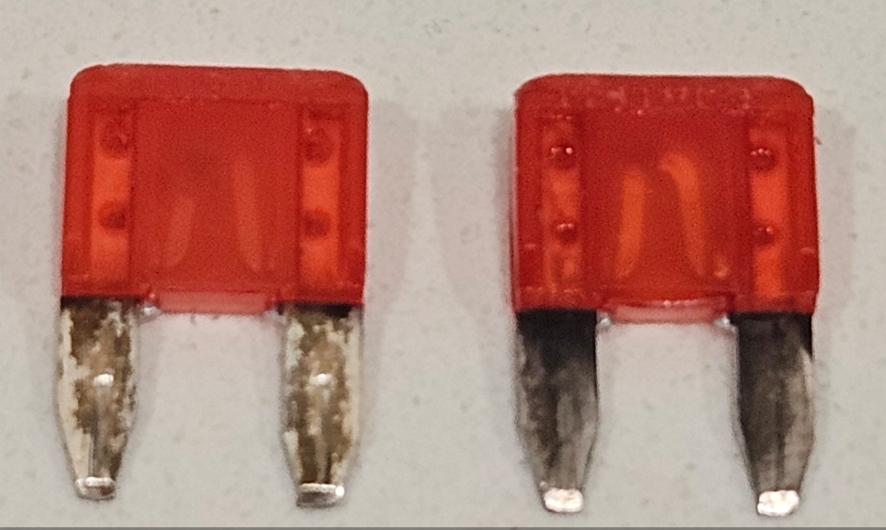
So I'll get a couple fuses, and backtrack my last couple steps. It's either from probing or from the RH visor as the LH visor and overhead console have been connected with everything working.
I wanted to double check the resistance to ground after the fuse was replaced to see if anything changed. Now I have 2....
So I'll get a couple fuses, and backtrack my last couple steps. It's either from probing or from the RH visor as the LH visor and overhead console have been connected with everything working.
when you are doing basically anything electrical, disconnect the battery first. the visors are live all the time, even with key offI replaced the fuse and so far alll seems to be working tonight.
I generally do, with the exception of bulbs for the most part. When I reconnected the visor I had the mirror flap closed but you're right, it's still a live circuit at the pigtail.when you are doing basically anything electrical, disconnect the battery first. the visors are live all the time, even with key off
Similar threads


- Replies
- 89
- Views
- 6K


