Installing aftermarket brake controller with factory ITBC (JL1)

Disclaimer: Links on this page pointing to Amazon, eBay and other sites may include affiliate code. If you click them and make a purchase, we may earn a small commission.

dkad260

Full Access Member
Joined
Jul 21, 2019
Posts
659
Reaction score
674
2012 Yukon XL Denali, has the factory integrated brake controller (JL1).

I wish to install the Tekonsha Prodigy P3 and would like to know if the GM wiring adapter from Tekonsha is needed for this.

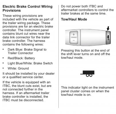
Does the taped up 4-wire bare leads exist if you have the ITBC?

Done messing with the non-working ITBC for now, running out of time to get things done.

Anyone who had installed an aftermarket controller with the integrated please chime in.


Edit to add:

Would an aftermarket be plug and play, or would I need to cut any of the factory wiring behind the 7-pin?

Thanks.
 
Last edited:
Joined
Apr 11, 2018
Posts
7,124
Reaction score
14,376
Location
St. Louis
Yes, you should still have the 4 wire leads taped up under the dash that the wire harness from the aftermarket controller gets spliced into
 
OP
OP
D

dkad260

Full Access Member
Joined
Jul 21, 2019
Posts
659
Reaction score
674
I wanted to add @swathdiver and @Joseph Garcia to this thread as I don't want to see any magic smoke.

Forgive me if I'm completely not recognizing the obvious....and that is in regards to the two red wires that get mounted to the studs outside the fuse box.

Since I have the JL1 factory controller, and I want to add an aftermarket controller, do I still connect the red wire that's between the fuse box and the fender?

I'm assuming that's the red wire that goes to the blunt end wires taped up next to the steering column behind the dash?

Do I also need to disconnect the factory brake control switch?
 
Joined
Apr 11, 2018
Posts
7,124
Reaction score
14,376
Location
St. Louis
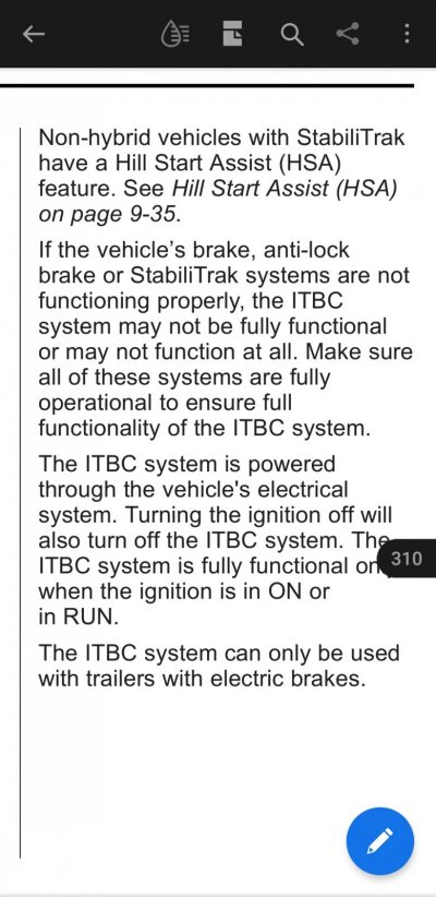
I don't have the ITBC, I installed an aftermarket one, but my manual says...

Screenshot_20220809-170347_Adobe Acrobat.jpg

With that being said, maybe the previous owner disconnected the ITBC to run an aftermarket one and that's why you can't get it to work. Do the 4 wires under the dash look like they've been used or are they still taped up good?
 
OP
OP
D

dkad260

Full Access Member
Joined
Jul 21, 2019
Posts
659
Reaction score
674
The wires were tucked in the tape outside the wire loom

Screenshot_20220809-181033_Gallery.jpg


Terminated as shown...

Screenshot_20220809-181048_Gallery.jpg
 
OP
OP
D

dkad260

Full Access Member
Joined
Jul 21, 2019
Posts
659
Reaction score
674
Thinking about you mentioning being taped up good....the last 2 GM's I wired up had electrical tape on the ends of all the wires, or taped up good as a bundle.

Three of these wires were bare but tucked away nicely.
 
OP
OP
D

dkad260

Full Access Member
Joined
Jul 21, 2019
Posts
659
Reaction score
674
Yes, that would definitely be one of concern if it wasn't.

I do have 12V on the light blue/white when the brake is pressed.
 
Joined
Apr 11, 2018
Posts
7,124
Reaction score
14,376
Location
St. Louis
I'm guessing they were previously hooked up and that's why the ITBC doesn't work. I'd test the other wires, or just the red with a volt meter and use the white as ground.

You do have the wire bundles by the underhood fuse box connected to the front posts?
 
OP
OP
D

dkad260

Full Access Member
Joined
Jul 21, 2019
Posts
659
Reaction score
674
I did connect the fender-side red to confirm 12V at 4-wire bundle.

Ground is good.

Here's the problem I think I'm going to face.

The blue wire at the 7-pin here,

Screenshot_20220809-185713_Gallery.jpg


Goes to the blue at the factory relay connector here.

Screenshot_20220809-185727_Gallery.jpg


So that begs the question, where does this blue wire that connects to the aftermarket brake controller go?

Screenshot_20220809-185658_Gallery.jpg


I'm not sold yet on these wires being used, maybe the tape is still up next to the wire loom.

I still show the factory controller working in the Tech 2, when I move the slider, the module sees the values change.


Do I need to run a length of wire from the controller to the 7-pin for the blue lead?

The JL1 option is nice, but becoming a massive headache..lol.
 
OP
OP
D

dkad260

Full Access Member
Joined
Jul 21, 2019
Posts
659
Reaction score
674
I'll check this tomorrow, but this mystery relay under the brake booster, might be part of this puzzle.

Screenshot_20220809-075226_Gallery.jpg


Screenshot_20220809-075257_Gallery.jpg
 
Joined
Apr 11, 2018
Posts
7,124
Reaction score
14,376
Location
St. Louis
I'll check this tomorrow, but this mystery relay under the brake booster, might be part of this puzzle.

View attachment 377618

View attachment 377619
I have that relay on mine (no JL1 or ITBC) and connected that wire to the driver's side stud in front of the box. The wire that's between the box and fender I connected to the passenger side stud. I did this when I wired my aftermarket brake controller.
 
Joined
Apr 11, 2018
Posts
7,124
Reaction score
14,376
Location
St. Louis
That blue wire under the dash is the brake control coming from a connected brake controller back to the 7 pin trailer plug.

On another note, the manual says that the ITBC will not connect to a trailer if there are any problems or DTCs in the brake, antilock, or stabilitrack systems.....

Screenshot_20220809-192157_Adobe Acrobat.jpg
 
OP
OP
D

dkad260

Full Access Member
Joined
Jul 21, 2019
Posts
659
Reaction score
674
That blue wire under the dash is the brake control coming from a connected brake controller back to the 7 pin trailer plug.

On another note, the manual says that the ITBC will not connect to a trailer if there are any problems or DTCs in the brake, antilock, or stabilitrack systems.....

Copy that....so I assume that the blue from the relay has to be tied into the blue under the dash in some form or fashion. I'm just trying to fully understand the system so bear with me.

I get the basics of the wiring, but not this JL1 setup.

@swathdiver did touch on the part about the codes. Problem is, I see there's a fault, but no codes are set.
 

swathdiver

Full Access Member
Joined
May 18, 2017
Posts
21,321
Reaction score
30,318
Location
Treasure Coast, Florida
1660120356945.png


That blue wire is referred to as D-BU in this diagram.

I am concerned about the notation in Tom's earlier post that says the blunt wires are disconnected further up in the wiring harness when a vehicle is equipped with JL1. There was a guy on here that fried his when he connected both.

Did you run a master scan across all modules at once for trouble codes?
 
OP
OP
D

dkad260

Full Access Member
Joined
Jul 21, 2019
Posts
659
Reaction score
674
I will run a scan on all the modules.


Looking at the 2nd schematic, this looks like it's a junction and should play nicely....unless I'm reading this incorrectly.

20220810_065034.jpg
 

swathdiver

Full Access Member
Joined
May 18, 2017
Posts
21,321
Reaction score
30,318
Location
Treasure Coast, Florida
I just went out to my truck and don't have that loose relay. I suspect that is part of your problem if it doesn't belong there.

@gpracer1 @Matthew Snyder

Do you guys have that relay around your brake booster as in Post #11? I don't but wanted to double check with those that have newer vehicles.
 

Forum statistics

Threads
138,087
Posts
1,998,593
Members
103,013
Latest member
GS Audio
Back
Top