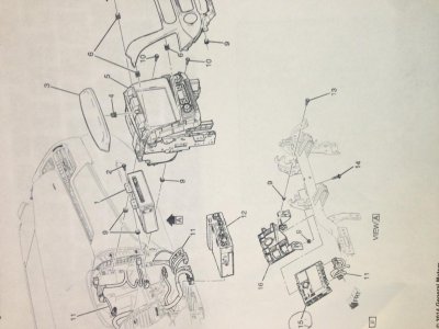
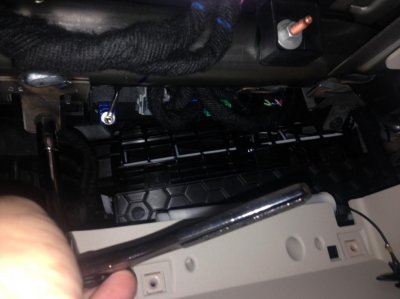
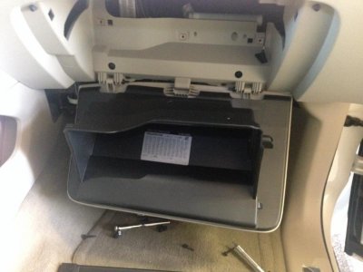
I'm trying to do this on my 2015 Escalade. So far the main difference appears to be that there are only 4 torx screws, and they are t15's. Well, t15 fit in there, it may actually be a slightly different size. I've now got the glove box fully removed and the black lining.
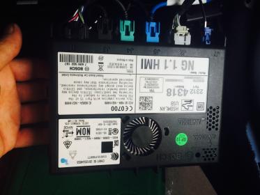
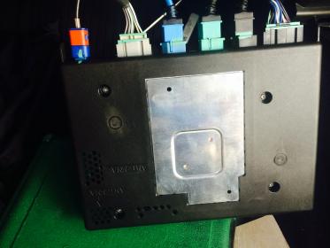
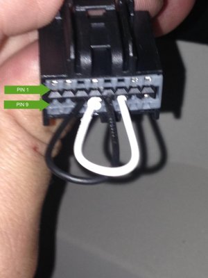
What is the trick to getting the blue antenna harness to disconnect? That''s the only one I'm struggling with at the moment.
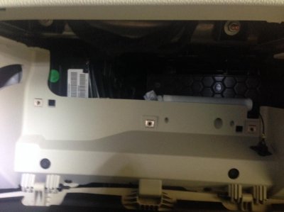
I don't think I'm going to attempt to bridge some connections. What if for some reason the Escalade wiring is slightly different and I bridge the wrong thing? Doesn't seem safe.
")