Removing the HMI Module

Disclaimer: Links on this page pointing to Amazon, eBay and other sites may include affiliate code. If you click them and make a purchase, we may earn a small commission.

steverkemp

TYF Newbie
Joined
Apr 16, 2014
Posts
21
Reaction score
0
Hello, I am trying to locate the HMI module. Does anyone have any tips as to where it is located- I've heard behind the glovebox. I'd like to document it for others to benefit but don't know where to start.
 

jmitchell

Full Access Member
Joined
Apr 3, 2014
Posts
182
Reaction score
4
I am going to take mine out first part of next week and send to Chris for programming. I will take pictures when I do. For now, let me look tonight and see if I can get a picture of it installed in place.
 
OP
OP
S

steverkemp

TYF Newbie
Joined
Apr 16, 2014
Posts
21
Reaction score
0
Schematic and Pictures so far

Looking at the attached schematic it appears that what Chris has indicated that the HMI is located under the glove box appears to be true. It will be nice if I don't have to get into the dash at all. I'll get into this later today and also try to take some pictures. The attached pictures of the front and back of the HMI are from Chris.
 

Attachments

  • 15_yukon_dash_schematic.jpg
    15_yukon_dash_schematic.jpg
    88.7 KB · Views: 324
  • hmifront.jpg
    hmifront.jpg
    16 KB · Views: 447
  • hmiback.jpg
    hmiback.jpg
    14 KB · Views: 420
Last edited:
OP
OP
S

steverkemp

TYF Newbie
Joined
Apr 16, 2014
Posts
21
Reaction score
0
Success

I was successful at removing the HMI today. I'll add pictures as soon as I can but here are the steps.

1. Open Glovebox and disconnect nylon spring line on right side.
2. Squeeze box to allow box to drop beyond stops and rest on floor board.
3. Remove 6 T-10 screws from black cover behind glovebox and remove black cover. There are 2 flanges on the top so gently pull down black cover once screws are removed.
4. Locate HMI and remove 6 harness connectors. You will be viewing it from the side that all of the connectors plug into.
5. Slide box out and towards you. (there are no screws to remove despite the fact that my pictures shows my wrench, it is an unnecessary step)
---Optional if you want to operate the vehicle without the HMI---
6. Jump pin 11 to 13 and 12 to 14 on the 16 pin female connector that was connected to location marked J1 on the HMI. IMPORTANT: SEE MY SUBSEQUENT POSTS ABOUT JUMPING THESE PINS!
 

Attachments

  • photo 1.jpg
    photo 1.jpg
    77.9 KB · Views: 305
  • photo 2.jpg
    photo 2.jpg
    91.1 KB · Views: 290
  • photo 3.jpg
    photo 3.jpg
    85.7 KB · Views: 274
Last edited:

jmitchell

Full Access Member
Joined
Apr 3, 2014
Posts
182
Reaction score
4
Thanks for the good info. Let's see those pics.

Do you have to jump the pins on the connector to get the vehicle to run without the HMI? I don't know if I want to mess with those. What do those pins represent?
 
OP
OP
S

steverkemp

TYF Newbie
Joined
Apr 16, 2014
Posts
21
Reaction score
0
Thanks for the good info. Let's see those pics.

Do you have to jump the pins on the connector to get the vehicle to run without the HMI? I don't know if I want to mess with those. What do those pins represent?

Attached picture of pin out. Jumping these pins is required to close the buslink communication loop to key vehicle systems. It will not fully operate with an open loop. The attached picture is of a spare connector for reference purpose only.
 

Attachments

  • 16-pin hmi.jpg
    16-pin hmi.jpg
    83.1 KB · Views: 152
Last edited:

jmitchell

Full Access Member
Joined
Apr 3, 2014
Posts
182
Reaction score
4
Ahhhh, I get it now, thanks for the picture. So you just use a separate piece of wire for each "Jump". Is there a specific wire that needs to be used or what did you use?
 
OP
OP
S

steverkemp

TYF Newbie
Joined
Apr 16, 2014
Posts
21
Reaction score
0
Something like a 20-22 gauge solid would be fine. Start smaller and move up until you get a snug fit. You want to avoid too large of gauge that could potentially over-stress the connector.
 

HAASTYL

TYF Newbie
Joined
Apr 20, 2014
Posts
8
Reaction score
0
Location
Iowa
Thanks Steve this is great! Now to get some free time to tear into things.

Much appreciated.
 
OP
OP
S

steverkemp

TYF Newbie
Joined
Apr 16, 2014
Posts
21
Reaction score
0
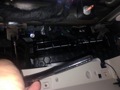
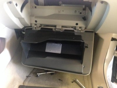
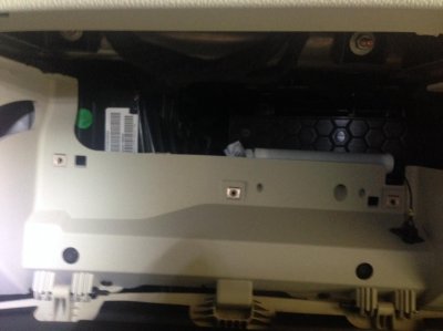
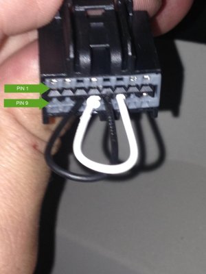
Hi all, I reinstalled the HMI yesterday and discovered that I damaged the jumped connectors with too thick of gauge wire. I had to repair the connector and will end up replacing it. It is CRITICAL that you do not overstress the connectors on female harness that you jump. I soldered a stranded 18 gauge and it was too big and I knew it after I inserted it. That is why I said before, please start with a very small 22 gauge sold wire and be very gentle. I'd love to hear others experience. If you aren't comfortable doing such then you should be prepared to leave the vehicle inoperable until you reinstall the HMI module.

I highly recommend testing the connection once you reinstall the HMI module before reassembling the glove box. With the vehicle running you should wiggle the J1 connector and make sure it has solid contact. Connection failure during operation could result in loss of key vehicle systems including power steering.
 
Top