You are using an out of date browser. It may not display this or other websites correctly.
You should upgrade or use an alternative browser.
You should upgrade or use an alternative browser.
Factory integrated brake controller not recognizing trailer.
- Thread starter dkad260
- Start date
Disclaimer: Links on this page pointing to Amazon, eBay and other sites may include affiliate code. If you click them and make a purchase, we may earn a small commission.
Update.
I hooked up the smaller ring terminal by itself and no luck. I removed the small terminal and hooked up the large ring terminal...again, no luck.
I then hooked up both terninals....no luck.
I lightly sanded the terminals to remove any oxidation as well.
I hooked up the smaller ring terminal by itself and no luck. I removed the small terminal and hooked up the large ring terminal...again, no luck.
I then hooked up both terninals....no luck.
I lightly sanded the terminals to remove any oxidation as well.
swathdiver
Full Access Member
Double check ALL of the fuses and specifically, 1, 3, 6, 25, 63 and 68. If that doesn't get it working, you're going to need a Tech-2 or something similar to test and diagnose this. There is a thread that shows where people live that would be happy to run it on your truck.
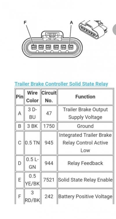
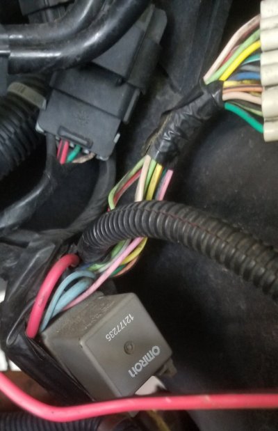
Behind the ABS module is the Solid State Relay (SSR), make sure that is plugged in. On the driver's side frame rail is where the ITB module resides, make sure it is connected and consider reseating the connector to make sure corrosion is not a factor.
If there are any Internal Chassis or BCM codes related to this, it will not work either. A basic code reader cannot see these codes.
Thanks, I will check those fuses in the AM, then climb underneath if needed.
I do have a Tech 2 and will double check for any codes.... nothing on the dash or DIC...yet.
Haven't done any troubleshooting with it in regards to the brake controller yet, but will check it out.
I do have a Tech 2 and will double check for any codes.... nothing on the dash or DIC...yet.
Haven't done any troubleshooting with it in regards to the brake controller yet, but will check it out.
swathdiver
Full Access Member
Awesome, fire up the Tech-2 tomorrow and run some diagnostics.Thanks, I will check those fuses in the AM, then climb underneath if needed.
I do have a Tech 2 and will double check for any codes.... nothing on the dash or DIC...yet.
Haven't done any troubleshooting with it in regards to the brake controller yet, but will check it out.
OK, that gets connected to the left terminal and you'll be all set then. If you want power to the inside the trailer, the other bundle of wires under the brake booster gets connected to the right terminal. Remember though, even when the truck is off, it is powering the trailer's interior with that wire connected.
Just wanted to touch on this for future reference for the sake of L vs R.
The wire under the brake booster has to go on the left terminal viewed from the driver's seat.
The wire next to the fender goes on the right terminal as viewed from the driver's seat.
Again, this was also clarified later as they are different sizes and can only be properly used one way...except the larger ring terminal could mistakenly be placed on both posts.
I have checked all the fuses listed earlier and all are good.
Will keep hunting.
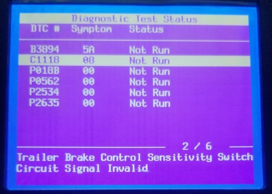
With the Tech 2, I was able to pull these codes, no idea how old they are.

With these current codes, as well as after I cleared them, still no brakes.
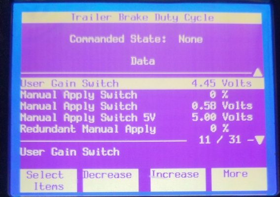
I was able to view the "Manual Apply Switch" percentage, and I could watch the values go from 0% to 100% as I moved the slider.

I went to the 7-pin on the rear of the Yukon, hooked my DMM to the ground and trailer brake terminal. I was getting a constant fluctuation from about 3.7 V to 4V. When I moved the slider or pressed the brake pedal, those values didn't change...kept fluctuating.
I checked the trailer's 7-pin connector and all the wires are clean and connected.

With these current codes, as well as after I cleared them, still no brakes.
I was able to view the "Manual Apply Switch" percentage, and I could watch the values go from 0% to 100% as I moved the slider.

I went to the 7-pin on the rear of the Yukon, hooked my DMM to the ground and trailer brake terminal. I was getting a constant fluctuation from about 3.7 V to 4V. When I moved the slider or pressed the brake pedal, those values didn't change...kept fluctuating.
I checked the trailer's 7-pin connector and all the wires are clean and connected.
swathdiver
Full Access Member
C1118 08
The TBCM detects the user gain switch is applied before the ignition is cycled OFF, and continuously applied for 30 seconds after ignition is cycled to ON.
The TBCM detects the user gain switch is applied continuously for 5 minutes.
The TBCM detects the user gain switch is applied before the ignition is cycled OFF, and continuously applied for 30 seconds after ignition is cycled to ON.
The TBCM detects the user gain switch is applied continuously for 5 minutes.
Circuit/System Testing
- Ignition OFF, disconnect the harness connector at the trailer brake controller switch.
- Test for less than 5 ohms between the low reference circuit terminal 8 and ground.
- If greater than the specified range, test the low reference circuit for an open/high resistance. If the circuit tests normal, replace the TBCM.
- Ignition ON, test for 4.8 - 5.2 volts between the 5-volt reference circuit terminal 3 and ground.
- If less than the specified range, test the 5-volt reference circuit for a short to ground or an open/high resistance. If the circuit tests normal, replace the TBCM.
- If greater than the specified range, test the 5-volt reference circuit for a short to voltage. If the circuit tests normal, replace the TBCM.
- Verify the scan tool Manual Apply Switch parameter is less than 5 percent.
- If greater than the specified range, test the signal circuit terminal 4 for a short to voltage. If the circuit tests normal, replace the TBCM.
- Install a 3A fused jumper wire between the signal circuit terminal 4 and the 5-volt reference circuit terminal 3. Verify the scan tool Manual Apply Switch parameter is greater than 90 percent.
- If less than the specified range, test the signal circuit for a short to ground or an open/high resistance. If the circuit tests normal, replace the TBCM.
- Verify the scan tool Redundant Manual Apply Switch parameter is greater than 90 percent.
- If less than the specified range, test the signal circuit terminal 5 for a short to voltage. If the circuit tests normal, replace the TBCM.
- Install a 3A fused jumper wire between the signal circuit terminal 5 and the 5-volt reference circuit terminal 3. Verify the scan tool Redundant Manual Apply Switch parameter is less than 2 percent.
- If greater than the specified range, test the signal circuit for a short to ground or an open/high resistance. If the circuit tests normal, replace the TBCM.
- Ignition ON, test for 4.8 - 5.2 volts between the signal circuit terminal 6 and ground.
- If less than the specified range, test the signal circuit for a short to ground or an open/high resistance. If the circuit tests normal, replace the TBCM.
- If greater than the specified range, test the signal circuit for a short to voltage. If the circuit tests normal, replace the TBCM.
- If all circuits test normal, test or replace the trailer brake controller switch panel.
Similar threads
- Replies
- 5
- Views
- 1K
- Replies
- 2
- Views
- 223
- Replies
- 2
- Views
- 1K
- Replies
- 15
- Views
- 5K


