mikez71
Full Access Member
- Joined
- Mar 9, 2023
- Posts
- 3,224
- Reaction score
- 3,993
1. Remove radio trim. (plastic prybar)
2. Remove switchbank under hvac controls (7mm socket)
3. Remove HVAC module. (7mm socket)
4. Re-pin/de-pin ~11 wires shown below (pin removal tool or fine pick)
5. Splice illumination wire (YE) from J1-4 switchbank plug to J2-1 HVAC module. (2' of wire and some splice connectors)
CJ3 Manual HVAC module
-----------------------------
'07-'09 have different climate control part numbers than '10-'14. MAKE SURE you get the RIGHT ONE!!!
Earlier models have an AC low pressure switch connected. Later models have the evap temp sensor.
J2 PLUG
----------
Manual control J2 plug is blue. Original automatic J2 plug is black.
It will not plug in directly, but looks like it should with a little modification to the lower alignment slots.
I de-pinned the wires, intending to re-pin them to the new connector. Reversible if problems.
The '07 plug I purchased has different pins than my '12 model.
So I ran the new J2 pigtail wires through the original unplugged pin receptacles, then heatshrinked around each wire/receptacle.
(I have since acquired a 2013 J2 blue connector which will accept the original pins from my 2012)
To remove the pins, first remove the retainer (J1 plug, pin style shown, enclosure retainer on older connectors)


Insert a fine pointy tool pointing to the bottom of the "T" slot, then pry upwards pointing to the top of the T to release the plastic tab holding pins in.
Pull wire while holding tool. (ebay pin removal tool shown)

WIRING CHANGES
---------------------
auto CJ2 (BLACK J2) -> manual CJ3 (BLUE J2)
J1-18 (PK) -> J1-8 (PAS AR TMP SW SIG)
J1-19 (GY) -> J1-18 (RR MOD MOT SIG)
J2-1 (RD/WH) -> J2-4 (HVAC BATT)
J2-8 (BK/WH) -> J2-3 (GROUND ZONE 18)
J2-9 (OG) -> J2-2 (HVAC MAN RUN)
J2-15 (BK) -> J2-10 (BKLT GND)
J2-10 (WH) -> J2-8 (RR DEFOG RLY CONT PWR)
J2-4 (L-GN/BK) -> J2-9 (OUTSIDE AIR TEMP)
J2-16 (D-GN) -> J2-12 (TEMP SENS COM LO REF)
J4-6 (GY/BK) -> J4-5 (LOW REF)
Wire below needs to be added for backlighting. Auto display has it's own brightness control that get's network data for dimmer level.
I spliced from switchbank wiring, also yellow wire.
J1-4 Switchbank plug (YE) ---SPLICE--> J2-1 (HVAC LED BKLT)
J1-3 / J1-6 can also be used if Cadillac switchbank.
-------------------------------------------------------------------------------------------
The wire below is UNUSED in the manual controls, *but* the module does have a pin in that location.
***UNPLUG*** this wire just in case!
--J3-3 (PU) RECIRC DR PSN SIG ---> UNPLUG
-------------------------------------------------------------------------------------------
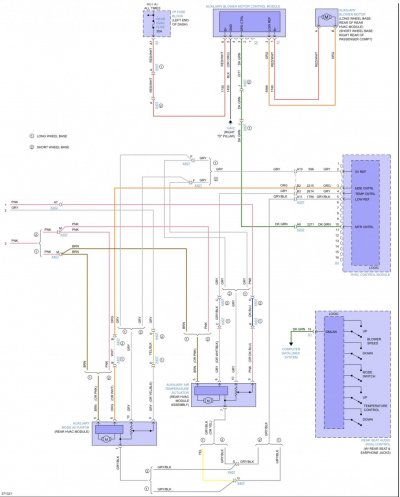
Stock wiring from a 2013 manual CJ3, some wires are for the rear roof mount dial controls, which are unused on my truck.

'10 thru '14 CJ3 manual models, the EVAP TEMP SENSOR ground is *SUPPOSED* to be connected to J3-19.
In the automatic controls, the evap ground was spliced with other grounds connected to J2-16.
(X2-16 in the charm.li diagrams for the automatic controls)
I left the original connection and seem to get a proper reading on the Tech2. I guess both ground pins are connected internally.
------------------------------------------------------------------------------------------
'07 thru '09 diagrams show an AC LOW PRESSURE SWITCH, that is wired to J2-6 (D-BU)
Other side of switch is grounded.
------------------------------------------------------------------------------------------
Unpopulated pins shown. J4-1 & J4-9 aren't visible, but they are vacant.
Camera too close. The circles are vacant, and the pins that look like they maybe in the same spot, are actually 1 or 2 pins over.

A big "THANK YOU!" to J91z and everyone who helped out!
2. Remove switchbank under hvac controls (7mm socket)
3. Remove HVAC module. (7mm socket)
4. Re-pin/de-pin ~11 wires shown below (pin removal tool or fine pick)
5. Splice illumination wire (YE) from J1-4 switchbank plug to J2-1 HVAC module. (2' of wire and some splice connectors)
CJ3 Manual HVAC module
-----------------------------
'07-'09 have different climate control part numbers than '10-'14. MAKE SURE you get the RIGHT ONE!!!
Earlier models have an AC low pressure switch connected. Later models have the evap temp sensor.
J2 PLUG
----------
Manual control J2 plug is blue. Original automatic J2 plug is black.
It will not plug in directly, but looks like it should with a little modification to the lower alignment slots.
I de-pinned the wires, intending to re-pin them to the new connector. Reversible if problems.
The '07 plug I purchased has different pins than my '12 model.
So I ran the new J2 pigtail wires through the original unplugged pin receptacles, then heatshrinked around each wire/receptacle.
(I have since acquired a 2013 J2 blue connector which will accept the original pins from my 2012)
To remove the pins, first remove the retainer (J1 plug, pin style shown, enclosure retainer on older connectors)
Insert a fine pointy tool pointing to the bottom of the "T" slot, then pry upwards pointing to the top of the T to release the plastic tab holding pins in.
Pull wire while holding tool. (ebay pin removal tool shown)
WIRING CHANGES
---------------------
auto CJ2 (BLACK J2) -> manual CJ3 (BLUE J2)
J1-18 (PK) -> J1-8 (PAS AR TMP SW SIG)
J1-19 (GY) -> J1-18 (RR MOD MOT SIG)
J2-1 (RD/WH) -> J2-4 (HVAC BATT)
J2-8 (BK/WH) -> J2-3 (GROUND ZONE 18)
J2-9 (OG) -> J2-2 (HVAC MAN RUN)
J2-15 (BK) -> J2-10 (BKLT GND)
J2-10 (WH) -> J2-8 (RR DEFOG RLY CONT PWR)
J2-4 (L-GN/BK) -> J2-9 (OUTSIDE AIR TEMP)
J2-16 (D-GN) -> J2-12 (TEMP SENS COM LO REF)
J4-6 (GY/BK) -> J4-5 (LOW REF)
Wire below needs to be added for backlighting. Auto display has it's own brightness control that get's network data for dimmer level.
I spliced from switchbank wiring, also yellow wire.
J1-4 Switchbank plug (YE) ---SPLICE--> J2-1 (HVAC LED BKLT)
J1-3 / J1-6 can also be used if Cadillac switchbank.
-------------------------------------------------------------------------------------------
The wire below is UNUSED in the manual controls, *but* the module does have a pin in that location.
***UNPLUG*** this wire just in case!
--J3-3 (PU) RECIRC DR PSN SIG ---> UNPLUG
-------------------------------------------------------------------------------------------
Stock wiring from a 2013 manual CJ3, some wires are for the rear roof mount dial controls, which are unused on my truck.
'10 thru '14 CJ3 manual models, the EVAP TEMP SENSOR ground is *SUPPOSED* to be connected to J3-19.
In the automatic controls, the evap ground was spliced with other grounds connected to J2-16.
(X2-16 in the charm.li diagrams for the automatic controls)
I left the original connection and seem to get a proper reading on the Tech2. I guess both ground pins are connected internally.
------------------------------------------------------------------------------------------
'07 thru '09 diagrams show an AC LOW PRESSURE SWITCH, that is wired to J2-6 (D-BU)
Other side of switch is grounded.
------------------------------------------------------------------------------------------
Unpopulated pins shown. J4-1 & J4-9 aren't visible, but they are vacant.
Camera too close. The circles are vacant, and the pins that look like they maybe in the same spot, are actually 1 or 2 pins over.
A big "THANK YOU!" to J91z and everyone who helped out!
Last edited: