2007 Tahoe - Wiring For Tweeters? Adding a Crossover?

Disclaimer: Links on this page pointing to Amazon, eBay and other sites may include affiliate code. If you click them and make a purchase, we may earn a small commission.

Tyler191938

TYF Newbie
Joined
Jan 30, 2021
Posts
8
Reaction score
5
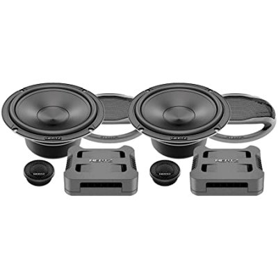
Hey pals, so I'm doing a component speaker upgrade on my 2007 Chevy Tahoe. I have a question about how to put in a crossover. From what I can tell it looks like the tweeters have four wires while the 6.5 door speaker only has 2. I'm guessing this means that it runs in parallel.

Does anyone have any experience or any ideas on how to put a crossover in the door to connect a brand new component setup? Thank you
 
Last edited:

Joseph Garcia

Supporting Member
Joined
Aug 2, 2018
Posts
6,500
Reaction score
8,500
It sounds like the power wires from the amp are going to the tweeters first, and then the 3rd and 4th wires are routed from the tweeters to the 6.5" door speakers. Yes, the tweeter and 6.5" speaker are running in parallel.

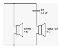
If you are using a simple 1 stage/order filter, that filter will be a non-polarized capacitor of a very specific capacitance value, which will filter out any sounds below a given frequency, usually around 80-100 HZ. This capacitor must be placed in series with the positive speaker wire going from the amp to the tweeter. In the wiring scenario that you describe that you are seeing, it would seem that the capacitor needs to be placed at the tweeter, rather than at the 6.5" speaker. The photo shows how the components should be wired.

woofer-tweeter wiring.jpg
 
OP
OP
T

Tyler191938

TYF Newbie
Joined
Jan 30, 2021
Posts
8
Reaction score
5
It sounds like the power wires from the amp are going to the tweeters first, and then the 3rd and 4th wires are routed from the tweeters to the 6.5" door speakers. Yes, the tweeter and 6.5" speaker are running in parallel.

If you are using a simple 1 stage/order filter, that filter will be a non-polarized capacitor of a very specific capacitance value, which will filter out any sounds below a given frequency, usually around 80-100 HZ. This capacitor must be placed in series with the positive speaker wire going from the amp to the tweeter. In the wiring scenario that you describe that you are seeing, it would seem that the capacitor needs to be placed at the tweeter, rather than at the 6.5" speaker. The photo shows how the components should be wired.

View attachment 353099
Hey, thank you so much for replying! You are indeed correct, the tweeter has 4 wires running to it and the 6.5" woofer in the door only has 2. After taking the A-Pillar tweeter out, I can see that there is a capacitor glued to the side of the tweeter.

With this being the case, what would be the best solution to install new component speakers? Do you think it would be best to take the 4 wires going into the tweeter, split them up, run them into the crossover, then split the tweeter and woofer from the crossover?

Thanks!
 
Last edited:

Joseph Garcia

Supporting Member
Joined
Aug 2, 2018
Posts
6,500
Reaction score
8,500
Hey, thank you so much for replying! You are indeed correct, the tweeter has 4 wires running to it and the 6.5" woofer in the door only has 2. After taking the A-Pillar tweeter out, I can see that there is a capacitor glued to the side of the tweeter.

With this being the case, what would be the best solution to install new component speakers? Do you think it would be best to take the 4 wires going into the tweeter, split them up, run them into the crossover, then split the tweeter and woofer from the crossover?

Thanks!
What you found is the most common configuration for a 1 stage/order high pass filter for a tweeter (capacitor literally glued to the tweeter, with the incoming + wire coming from the + speaker output terminal from the amp connected to the capacitor, and then the other end of the capacitor connected to the + terminal on the tweeter (often identified by a red or other color dot of paint next to the + terminal). Since the capacitor is non-polarized, it does not matter which end of the capacitor gets connected to the amp side or to the tweeter side.

I am assuming that you are going to place the new tweeter directly in the existing A pillar tweeter location and the new midrange speaker placed directly in the door's existing speaker location. You will need to identify at the A pillar which 2 wires are coming from the amp, and which 2 wires are going to the 6.5" door speakers. You can do this with a simple ohm meter, by connecting one lead to the wire on one of the tweeter terminals, and then connecting the other lead of the ohm meter to one of the 6.5" door speaker terminals. Using this method, you should be able to identify which 2 of the 4 wires connected to the tweeter go to the 6.5" speakers, including which wire is the + wire, and which wire is the - wire (one of the terminals on the 6.5" speaker will probably also be identified with a dot, indicating that one is the + terminal).

If your new component system still has a simple 1 stage/order high pass filter in the form of a capacitor, then when installing the new tweeter, connect the + wire from the amp to BOTH one side of the capacitor and to the + wire running to the 6.5" door speaker. Then connect the other side of the capacitor to the + terminal of the tweeter. Connect the - wire coming from the amp to BOTH the - terminal on the tweeter and the - wire running to the 6.5" door speaker.

If you are installing a more sophisticated crossover network with separate midrange and tweeter output terminals for each channel, there are a few ways to wire it, depending upon if you want to dig down to expose the amp and and directly access its connections, or if you want to try to repurpose existing wires and minimize long runs of new wire. Again, there is more then one way to accomplish this, and some folks have specific preferences on these installations.


If it were me doing the work, I would suggest the following, as I do not like to dig down any further than I have to, to access buried components, like an amp. Find a place out of sight to install the crossover network (hopefully, up under the dash). Then, in the A pillars, I would identify which 2 of the 4 wires are coming from the amp, and of those 2 wires, which wire is the + wire and which wire is the - wire. You should be able to identify this by exception, after you have used the ohm meter process mentioned above to identify the 2 wires going to the 6.5" door speaker.

I would then run 6 new wires (3 pairs of speaker wire) from the crossover's location to each A pillar location. This should be very easy to perform, using an electrician's wiring snake, by snaking all 3 pairs of wires at once. 1 pair will be used to redirect the amp's output wires from the A pillar to the crossover's input terminals, and the other 2 pairs will connect the crossover's appropriate output terminals to the tweeter terminals in the A pillar and to the wires going to the 6.5"door speakers. Keep the + and - wires properly aligned for all 3 pairs of wires.
 
OP
OP
T

Tyler191938

TYF Newbie
Joined
Jan 30, 2021
Posts
8
Reaction score
5
If it were me doing the work, I would suggest the following, as I do not like to dig down any further than I have to, to access buried components, like an amp. Find a place out of sight to install the crossover network (hopefully, up under the dash). Then, in the A pillars, I would identify which 2 of the 4 wires are coming from the amp, and of those 2 wires, which wire is the + wire and which wire is the - wire. You should be able to identify this by exception, after you have used the ohm meter process mentioned above to identify the 2 wires going to the 6.5" door speaker.

I would then run 6 new wires (3 pairs of speaker wire) from the crossover's location to each A pillar location. This should be very easy to perform, using an electrician's wiring snake, by snaking all 3 pairs of wires at once. 1 pair will be used to redirect the amp's output wires from the A pillar to the crossover's input terminals, and the other 2 pairs will connect the crossover's appropriate output terminals to the tweeter terminals in the A pillar and to the wires going to the 6.5"door speakers. Keep the + and - wires properly aligned for all 3 pairs of wires.
That makes sense. I was really hoping I wouldn't have to run all new wire but I know if I do that it will hold up and will be installed correctly. I originally was going to run a pair of speaker wire into the door and up to the tweeter. That's because I was going to grab the incoming door wire and that would go straight into the crossover, then I'd run a new cable to the 6.5" woofer, then the other speaker cable up to the tweeter. I'm really not a fan of snaking wire through the door jam boot so I was trying to avoid this and just grabbing all the connections at the A-Pillar tweeter, put the crossover under the dash, and run a new line to the tweeter and use the existing wire going to the 6.5" woofer.

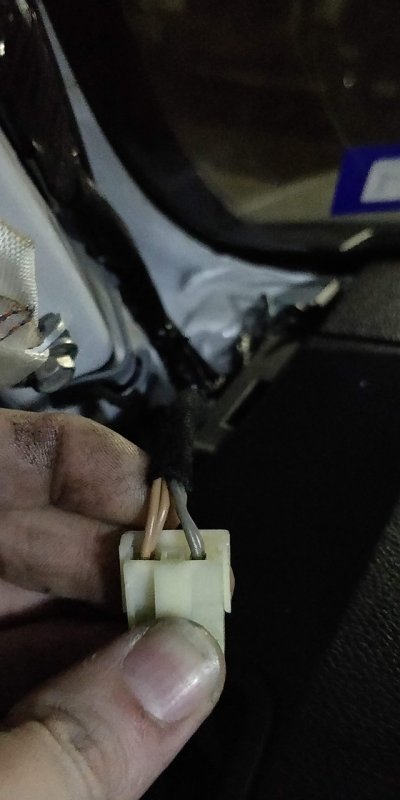
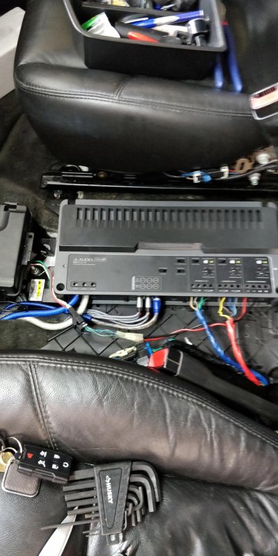
I think I'm just going to run all new speaker cable. I'll put some pics below, and you'll see I'm already pretty deep into it, as I've already mounted a JL Audio RD900/5 under the center console and have done the BOSE delete.

IMG-20210316-012241.jpg
IMG-20210226-135020.jpg
71a-M2-Tfbon-L-AC-SS450.jpg
 

Joseph Garcia

Supporting Member
Joined
Aug 2, 2018
Posts
6,500
Reaction score
8,500
That makes sense. I was really hoping I wouldn't have to run all new wire but I know if I do that it will hold up and will be installed correctly. I originally was going to run a pair of speaker wire into the door and up to the tweeter. That's because I was going to grab the incoming door wire and that would go straight into the crossover, then I'd run a new cable to the 6.5" woofer, then the other speaker cable up to the tweeter. I'm really not a fan of snaking wire through the door jam boot so I was trying to avoid this and just grabbing all the connections at the A-Pillar tweeter, put the crossover under the dash, and run a new line to the tweeter and use the existing wire going to the 6.5" woofer.

I think I'm just going to run all new speaker cable. I'll put some pics below, and you'll see I'm already pretty deep into it, as I've already mounted a JL Audio RD900/5 under the center console and have done the BOSE delete.

View attachment 353146
View attachment 353147
View attachment 353148
I always use existing stock speaker wire where I can, as it is perfectly capable of handling the power that the new system will produce.

You can certainly run the wire is the way that you describe, and it will get you to the same end point. I never like trying to thread wire through the door jam boot, so I just don't do it. I've always found running wires through the A pillar to be easy, since it is basically an open shaftway.

I wish you the best of outcomes on your audio project, and I'm sure that you will be very happy with it.
 
OP
OP
T

Tyler191938

TYF Newbie
Joined
Jan 30, 2021
Posts
8
Reaction score
5
I always use existing stock speaker wire where I can, as it is perfectly capable of handling the power that the new system will produce.

You can certainly run the wire is the way that you describe, and it will get you to the same end point. I never like trying to thread wire through the door jam boot, so I just don't do it. I've always found running wires through the A pillar to be easy, since it is basically an open shaftway.

I wish you the best of outcomes on your audio project, and I'm sure that you will be very happy with it.
Thank you so much for all your input. You've been a huge help.
 

Forum statistics

Threads
129,185
Posts
1,811,828
Members
92,287
Latest member
cartman
Top