J5races
Member
- Joined
- Feb 3, 2023
- Posts
- 53
- Reaction score
- 34
Hello all, new member but been lurking for a while now. I’m adding a Whipple Gen V kit to my 2018 Tahoe RST when it arrives.
I bought an Innovative PSB-1 AFR and boost gauge. I have a few questions:
1) where should I have a bung installed for most accurate AFR? I realize I’ll only be looking at one bank of cyl
2)Where should I get my boost reference for the gauge?
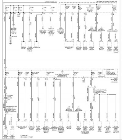
3)Which wires do I tap into by the driver foot area to get the lights/switched power/etc for this gauge? I’m good with wiring just need to know what wires are what I need. I’m extremely handy with a soldering iron. But don’t know the Pino it’s of the Tahoe
Thanks all!
Jon
I bought an Innovative PSB-1 AFR and boost gauge. I have a few questions:
1) where should I have a bung installed for most accurate AFR? I realize I’ll only be looking at one bank of cyl
2)Where should I get my boost reference for the gauge?
3)Which wires do I tap into by the driver foot area to get the lights/switched power/etc for this gauge? I’m good with wiring just need to know what wires are what I need. I’m extremely handy with a soldering iron. But don’t know the Pino it’s of the Tahoe
Thanks all!
Jon