Where to mount resistors for LED taillight bulbs?

Disclaimer: Links on this page pointing to Amazon, eBay and other sites may include affiliate code. If you click them and make a purchase, we may earn a small commission.

CASTLEDFW15

Full Access Member
Joined
Aug 21, 2021
Posts
291
Reaction score
110
Location
North TX
I am getting the equipment in order and all equipment should be here in the next few days.
 

CASTLEDFW15

Full Access Member
Joined
Aug 21, 2021
Posts
291
Reaction score
110
Location
North TX
This is some file photos from the last time I did the LED conversion. These are in progress photos not the final product. These should be able to at least visualize the concept. When the resistors are installed to the mounting plate then it can be trimmed a bit more. When the mounting plate is in its final design, then the Velcro is attached. The other end of the Velcro is mounted to the frame in the approximate final spot. The Velcro idea maintains the mounting point but allows for simple removal and cutting of the resistor wires without interfering with the power and grounding wires of the bulb circuit.

Also not the washers between the resistor and plate. That’s your room for air circulation and to thread some Aluminum foil around the resistor to hold the heat on the resistor and prevent melting of the plastic trim, wire insulation etc….since the resistor doesn’t actually touch the plate in theory the heat from resistor shouldn’t transfer to the plate etc…..

Sorry the bonus photo was the 22” Gloss Black wheels with Michelin Defender’s
 

Attachments

  • 891A798D-7D81-4A9E-B936-6DEAB542ECA7.jpeg
    891A798D-7D81-4A9E-B936-6DEAB542ECA7.jpeg
    326.3 KB · Views: 7
  • 6108DF52-99CA-484A-9804-AC2B68BCC6A5.jpeg
    6108DF52-99CA-484A-9804-AC2B68BCC6A5.jpeg
    174.3 KB · Views: 8
  • D1719C1C-0BA1-4EED-972F-41C07D68E51C.jpeg
    D1719C1C-0BA1-4EED-972F-41C07D68E51C.jpeg
    330.8 KB · Views: 7
  • F331955B-5F4D-43D7-898F-C8E7425D15C5.jpeg
    F331955B-5F4D-43D7-898F-C8E7425D15C5.jpeg
    448.4 KB · Views: 7
  • DC7F11CC-6305-4F32-B374-CDB2210ACFF4.jpeg
    DC7F11CC-6305-4F32-B374-CDB2210ACFF4.jpeg
    442.2 KB · Views: 7

Fless

Staff member
Super Moderator
Joined
Apr 2, 2017
Posts
10,565
Reaction score
21,031
Location
Elev 5,280
That last pic -- seems like the foil around the heat sink would defeat the purpose.
 

Joseph Garcia

Supporting Member
Joined
Aug 2, 2018
Posts
6,604
Reaction score
8,673
On my '07, I did not receive any error lights on the dashboard, when I converted the truck to all LEDs. I do have hyperflash with the directionals, but I believe that the fast flash attracts more attention from other motorists, and after all, that is the purpose of the directional signals in the first place.

So, no resistors on my truck.
 

CASTLEDFW15

Full Access Member
Joined
Aug 21, 2021
Posts
291
Reaction score
110
Location
North TX
Fless,

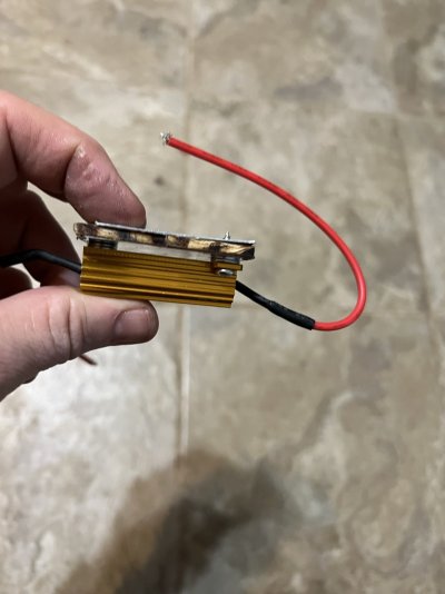
You are nt the only one to consider the heat sink angle. U had them in there for seven months with no issues. The other thought although not verified by electrical engineers with certified calibrated test equipment…..Electro Magnetic Interference (EMI).

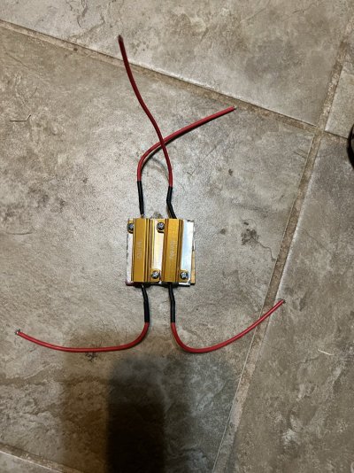
After the installation I had no hyper flash, no CANBUS errors, perfectly timed and sequenced turn brake and back up light application. The model bulb I used was ALLA 7440/7443/T921 bulbs. Brake and Reverse lights were a three flash then solid bulbs. Turn signals were Amber LED but didnt have to worry about the three flash first.

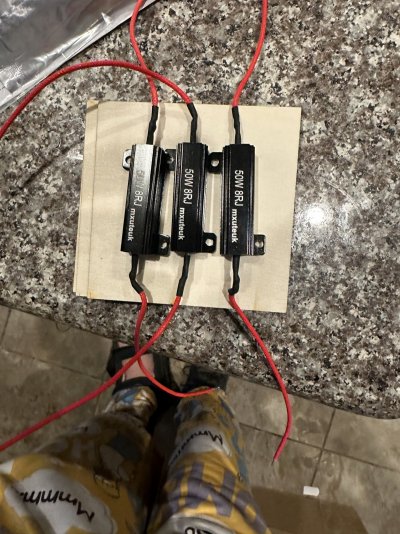
With almost a year of the LED upgrade spread across two different vehicles I only had the CANBUS Error. The typical Resistor heated up during extended traffic delays. The CANBUS error was turn signal related. After the turn was made and resistor cooled off no further issues.

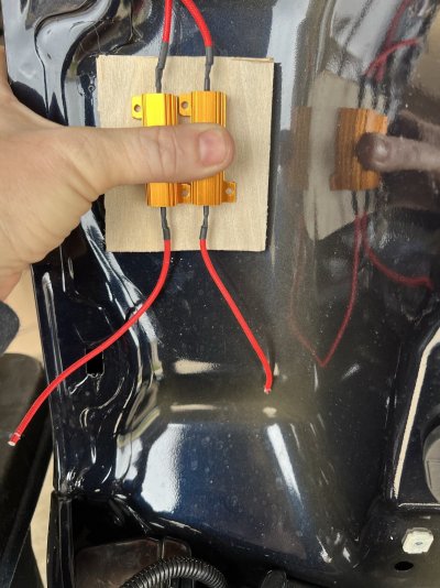
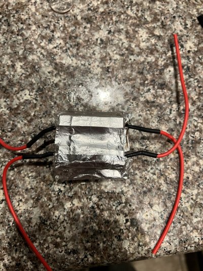
I admit I might have gone a bit overkill on the Aluminum foil but think about this. If the bulbs are installed correctly, resistors are wired correctly and mounting plate is oriented correctly….…..The lens and bulbs should never have to be removed again. This area for the most part is not a common inspection item. Unless the lens assembly is removed for some other reason then this is a set and forget item.

If the lens assembly does have to be removed for whatever reason, then probably a good as time as any to check the areas for melting, (plastic lens assembly, wiring etc…)
 

CASTLEDFW15

Full Access Member
Joined
Aug 21, 2021
Posts
291
Reaction score
110
Location
North TX
This is one quick photo to show the overview of my mounting plate. The 4X4 pieces of wood might need to be trimmed but that’s what wood cutoff wheels for the Dremel Tool are for. After that splicr the wires into the bulb connectors. It really doesn’t matter which wire is where as long as the Positive and Negative wires are spliced into correctly.
 

Attachments

  • 4C839FDB-F82C-4395-929E-0E82A56A0D27.jpeg
    4C839FDB-F82C-4395-929E-0E82A56A0D27.jpeg
    429.9 KB · Views: 5
Top