Problem with rear heat

Disclaimer: Links on this page pointing to Amazon, eBay and other sites may include affiliate code. If you click them and make a purchase, we may earn a small commission.

shorelocal

Member
Joined
Aug 15, 2021
Posts
33
Reaction score
31
Location
BC, Canada
I've searched and read through the various posts here and I still can't get my rear heat working 100%

Situation I have is that I can't change from cold to hot ... it's always cold. I can change the fan speed (ceiling left hand knob) and I can change the blend direction from floor to ceiling (ceiling right hand knob), but the hot and cold knob doesn't change the temp.

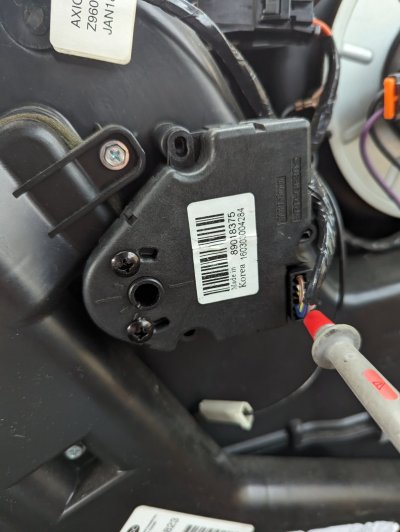
I've swapped the rear actuators and they both work on the floor to ceiling direction change, so assume both actuators are good.

I've swapped out the control module for one from an '03 Suburban and same issue. I've even swapped out the actuators from the 03 Suburban, same issue.

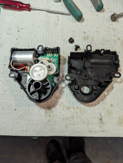
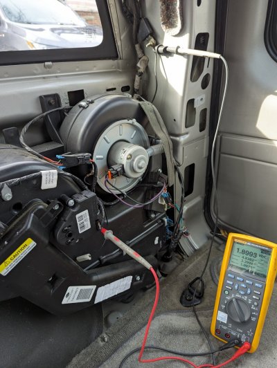
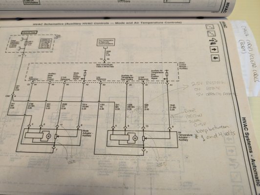
I've performed the calibration procedure multiple times ... no fix. However, when I manually open up the hot/cold actuator (which is always out of range) and reset it so that it is between the hash marks and center of the range, as soon as I complete the calibration process, the actuator turns to the far right (clockwise) and out of range of the hash marks. Does this mean that the control module is working correctly and commanding the actuator to max cold? BTW ... it's done this with multiple different actuators.

Finally, I've pulled the ceiling controls apart and sprayed some contact cleaner into the middle knob (hot/cold) and no change.

I'm stumped. Barring replacing the ceiling controls with a different junkyard unit, not sure what to do.

Anyone else had this issue and know the fix?
 
OP
OP
S

shorelocal

Member
Joined
Aug 15, 2021
Posts
33
Reaction score
31
Location
BC, Canada
Forgot to mention ... I can manually move the hot/cold blend door tab and it does alter the air coming out of the vents, so the actual blend door is intact.
 

MassHoe04

Full Access Member
Joined
Nov 4, 2021
Posts
1,586
Reaction score
2,796
Location
Western MA
If you have a Tech 2 scan tool, you could try this:
Heater Mode – Body > Heating and Air Conditioning > Special Functions > Miscellaneous Test

If not, you could also try this:
Put the left knob on the overhead control panel up front to AUX.
See if you can get the control panel on the back of the center console to crank heat out the back vents.

If you can get that to send heat, adjust temp up/down and make it come out the top/bottom or both vents from the middle row control panel, then it would be a control issue in the overhead switch up front.

If still nothing, I would look to see what voltages are at the connector that attaches to the blend door actuator. I don't know what wire is supposed to read what voltage when things on the control change. Someone else here should be able to advise on what those readings should be using your multi-meter.
 

Badia358

TYF Newbie
Joined
Mar 29, 2023
Posts
2
Reaction score
1
If you have a Tech 2 scan tool, you could try this:
Heater Mode – Body > Heating and Air Conditioning > Special Functions > Miscellaneous Test

If not, you could also try this:
Put the left knob on the overhead control panel up front to AUX.
See if you can get the control panel on the back of the center console to crank heat out the back vents.

If you can get that to send heat, adjust temp up/down and make it come out the top/bottom or both vents from the middle row control panel, then it would be a control issue in the overhead switch up front.

If still nothing, I would look to see what voltages are at the connector that attaches to the blend door actuator. I don't know what wire is supposed to read what voltage when things on the control change.top to bottom. Someone else here should be able to advise on what those readings should be using your multi-meter.
I am having the same problem. No heat at the rear and only cold air. I have replaced the actuator and the control module and still the same problem. I compared voltages on the connector for the 2 rear actuators. The one that works (upper/lower airflow control) has a voltage change on the White/Black wire of the actuator connector when it moves from top to bottom, but the the actuator that controls hot and cold does not have a voltage move on the White/Black wire of the actuator connector.

Hoping that someone has resolved this issue.
 

MassHoe04

Full Access Member
Joined
Nov 4, 2021
Posts
1,586
Reaction score
2,796
Location
Western MA
How does heat flow to the back, normally?
Basically same setup and mechanisms in the rear HVAC box as up front, except the rear box does not have added complexities of dealing with controlling left or right. Just open/close doors for hot/cold and top/bottom ducts. One other difference for the rear HVAC is two control modules (overhead console for front row control over rear system and on the back of the center console for 2nd row passenger control of the system).

The rear box is simpler because it has less moving stuff.
But there are more things trying to issue commands and control what it does.

Maybe this isn't your question... or is it?
 

S33k3r

Full Access Member
Joined
Aug 14, 2017
Posts
2,254
Reaction score
2,977
Location
Dallas, Texas
I was just trying to think of what would stop the flow of warm air to the back. So yes -- thank you -- you did answer my question.
 

Badia358

TYF Newbie
Joined
Mar 29, 2023
Posts
2
Reaction score
1
I measured the voltages on each pin. Not sure of the actual pin number for the connector, but on the Blue (or Purple) wire I get a reading of zero (0) volts on the actuator that controls hot and cold no matter where I set the hot/cold control. On the actuator that controls the air for top/bottom, this voltage changes from 1.81 volts to 4.21 volts as I move the controls from bottom to top. I am guessing that this wire is the sense wire coming from the actuator to tell the controller board the position of the actuator. Just not sure why it is always zero (0) volts. I also checked to see if this wire was shortage and it is not. Here are all the voltages with vehicle engine running.

Wire Color Hot Cold Comments
Brown 14V 14V I am sure that this is power to the actuator
White/Yellow 0V 2.44V
Yellow 0V 0V
Blue or Purple 0V 0V This voltage should change as you move hot/cold
Gary 4.86V 4.86V

Almost seems like a bad actuator, but I replaced it twice with a new actuator and I also replace the controller with a used control since unable to find a new controller.

Would love to hear when someone figures this issue out
 

LordWayback

Full Access Member
Joined
Jun 23, 2022
Posts
509
Reaction score
399
I measured the voltages on each pin. Not sure of the actual pin number for the connector, but on the Blue (or Purple) wire I get a reading of zero (0) volts on the actuator that controls hot and cold no matter where I set the hot/cold control. On the actuator that controls the air for top/bottom, this voltage changes from 1.81 volts to 4.21 volts as I move the controls from bottom to top. I am guessing that this wire is the sense wire coming from the actuator to tell the controller board the position of the actuator. Just not sure why it is always zero (0) volts. I also checked to see if this wire was shortage and it is not. Here are all the voltages with vehicle engine running.

Wire Color Hot Cold Comments
Brown 14V 14V I am sure that this is power to the actuator
White/Yellow 0V 2.44V
Yellow 0V 0V
Blue or Purple 0V 0V This voltage should change as you move hot/cold
Gary 4.86V 4.86V

Almost seems like a bad actuator, but I replaced it twice with a new actuator and I also replace the controller with a used control since unable to find a new controller.

Would love to hear when someone figures this issue out
Pull down the rear control panel without removing the connector and test the pins for power directly from the back of the control panel while powered if you get power at the control panel it’s a short in the wire if you don’t get power directly from the panel bingo panel I’ve gotten multiple bad blend door actuators so I wouldn’t put it out of the realm of possibility
 

Gabefo

TYF Newbie
Joined
Jan 7, 2024
Posts
2
Reaction score
3
I measured the voltages on each pin. Not sure of the actual pin number for the connector, but on the Blue (or Purple) wire I get a reading of zero (0) volts on the actuator that controls hot and cold no matter where I set the hot/cold control. On the actuator that controls the air for top/bottom, this voltage changes from 1.81 volts to 4.21 volts as I move the controls from bottom to top. I am guessing that this wire is the sense wire coming from the actuator to tell the controller board the position of the actuator. Just not sure why it is always zero (0) volts. I also checked to see if this wire was shortage and it is not. Here are all the voltages with vehicle engine running.

Wire Color Hot Cold Comments
Brown 14V 14V I am sure that this is power to the actuator
White/Yellow 0V 2.44V
Yellow 0V 0V
Blue or Purple 0V 0V This voltage should change as you move hot/cold
Gary 4.86V 4.86V

Almost seems like a bad actuator, but I replaced it twice with a new actuator and I also replace the controller with a used control since unable to find a new controller.

Would love to hear when someone figures this issue out
Solved:
I struggled with the same problem on my 05 Yukon, except it was for the rear AUX heater. After lots of diagnosing and realizing there was nothing wrong with the actuator or the control module, I realized that the feedback circuit that tells the control what position the door is in was out of range. It should read between about 1 and about 4 volts depending on the position. If it reads close to zero or close to 5 volts then the acutator will stay in the extreme position and will not move. Use a volt meter and measure pin 9 of the actuator, it should be the dark blue wire. If its out of range, remove the actuator, open the acutator and reposition the gear then place something at the stops to prevent the gear or arm from allowing it to turn beyond the extreme ends. Reinstall and initialize the control by removing battery power or the HVAC fuse for about a minute. Measure pin 9 and confirm your voltage stays between 1 and 4 volts at the extreme end of door movement. Easy fix but complicated explaination. Oh and the actuator pins start at 5 and go to 10. Pin 8 should be missing if our acuators are the same. Good luck.

See pics. I used two black philips screws (pic 2) to keep the actuator gear from rotating too far. The screws are just "Stops" to keep the gear from going too far. Before the screws I had 5 volts, after I got betwen 1.2 and 4.2 volts. Remember in electronics, logical signals are never zero and 5, they are actually silghty over 0 and under 5. The screws are there because likely the door is old and over travels which causes the actuator to over travel which causes the door position voltage to go to the extreme ends during acuator calibration. see pics and good luck. What a relief to finally solve this!
 

Attachments

  • PXL_20240114_174943067.jpg
    PXL_20240114_174943067.jpg
    320.3 KB · Views: 10
  • PXL_20240114_183726414.jpg
    PXL_20240114_183726414.jpg
    214.6 KB · Views: 9
  • PXL_20240114_185512000.MP.jpg
    PXL_20240114_185512000.MP.jpg
    338 KB · Views: 10
  • PXL_20240114_194757106.jpg
    PXL_20240114_194757106.jpg
    258.6 KB · Views: 10
Last edited:

Forum statistics

Threads
128,790
Posts
1,805,493
Members
91,772
Latest member
dvnt
Top