ABS controller needed

Disclaimer: Links on this page pointing to Amazon, eBay and other sites may include affiliate code. If you click them and make a purchase, we may earn a small commission.

Tbruz

Full Access Member
Joined
Feb 1, 2011
Posts
549
Reaction score
58
Location
Windham NH
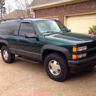
1997 Tahoe 2 door with 5.7L.
Getting a ABS light on my dash and my mechanic says its the ABS control module gone bad.
Per the local Chevy dealer my VIN needs GM part 12389541 but its NLA.
Cant seem to locate anything at the local VIP/ORiellys ; any suggestions where I might be able to get a ABS controller short of a junkyard.
Thanks in advance.
Tbruz

 

Tonyrodz

Resident Resident
Joined
Feb 16, 2012
Posts
33,344
Reaction score
51,835
Location
Central Jersey
1997 Tahoe 2 door with 5.7L.
Getting a ABS light on my dash and my mechanic says its the ABS control module gone bad.
Per the local Chevy dealer my VIN needs GM part 12389541 but its NLA.
Cant seem to locate anything at the local VIP/ORiellys ; any suggestions where I might be able to get a ABS controller short of a junkyard.
Thanks in advance.
Tbruz

Is it rebuildable?
 
OP
OP
T

Tbruz

Full Access Member
Joined
Feb 1, 2011
Posts
549
Reaction score
58
Location
Windham NH
Have not been able to locate one that rebuilds 1997 ABS. Found a couple that rebuild GM 1999 to present.
Tbruz
 
OP
OP
T

Tbruz

Full Access Member
Joined
Feb 1, 2011
Posts
549
Reaction score
58
Location
Windham NH
Thanks for that lead Doubeleive, I may have to get a JY one if I cant locate a rebuilder.
Tbruz
 

east302

Full Access Member
Joined
Dec 21, 2016
Posts
1,688
Reaction score
1,688
Location
Mississippi
You might contact some of those online rebuilders, I would think that they would be able to work on any of the Kelsey Hayes units.

Can you do without the truck in the meantime? If not, I’d pick up one from a salvage yard and swap it out. Just grab the whole thing instead of asking it to be separated. That would be the control module on top, the modulating valve beneath and the combination valve that the brake lines connect to.

a4028fe6b7425b18277b5a9bce19767b.jpg


Afterwards, have a shop use a scanner to run the automated ABS bleed sequence to get the air out of it. Follow that with a bleed at all four corners.

Car-part.com is a good search engine for local yards.


Sent from my iPhone using Tapatalk
 
OP
OP
T

Tbruz

Full Access Member
Joined
Feb 1, 2011
Posts
549
Reaction score
58
Location
Windham NH
I've got a unit coming to me from a Southern JY in the next day or so. I have already popped off the ABS module on my ride so it will be an easy swap once it arrives.
There are probably 25 companies that rebuild the 99 onward Kelsey Hayes 325 units but no one rebuilds the 94-98 chevy with Kelsey Hayes 310 ABS units.
Our only option is a JY unit that is in unknown condition, unless East302 wants to send me that ABS module in his picture .....IF its a know good one that is.
Thanks
Tbruz
 

east302

Full Access Member
Joined
Dec 21, 2016
Posts
1,688
Reaction score
1,688
Location
Mississippi
That’s good information to have, I didn’t know that the earlier units were not being rebuilt.

That’s an old picture, but it was a junkyard unit that I gave $75 for. Hopefully the one on the way works out.


Sent from my iPhone using Tapatalk
 
OP
OP
T

Tbruz

Full Access Member
Joined
Feb 1, 2011
Posts
549
Reaction score
58
Location
Windham NH
I received and installed the JY ABS controller tonight with no change in the ABS status; the light is still on indicting no ABS function.
Since I can't communicate with two controllers now, I'm at a loss for next steps:
60 amp ABS fuse under hood is confirmed good.
Searching for a willing candidate to swap my Kesley Hayes 310 module into there ride to confirm if my original module is good or bad.
I'm actually contemplating visiting the local GM dealership to let them diagnose with their tools.

Any other ideas appreciated.

While its really no big deal if I don't have ABS, I will admit I am a bit OCD and I like to have all features working as intended. Plus a light on my dash makes me nuts and I cant just remove the bulb out, that's cheating!
Thank in advance
Tbruz
 
Last edited:

east302

Full Access Member
Joined
Dec 21, 2016
Posts
1,688
Reaction score
1,688
Location
Mississippi
What code is being set?

Assuming the scanner cannot communicate with the brake control module, start at step 4 in the table below. Otherwise, let me know what code is being thrown and I’ll pass along the diagnostic tables for that.

efe3724349fc6a7a93688778b57050e2.jpg


8e437e441157a796ea3fb372f8b5f5ec.gif


2cd14e84fbbe98cd4b66d7ba23ef5d24.jpg


157cf724a0f6c8d586b0b8c8ce71680e.gif


b9f1a6a388a4b586bb761d85f63feb85.gif


Sent from my iPhone using Tapatalk
 
Last edited:
OP
OP
T

Tbruz

Full Access Member
Joined
Feb 1, 2011
Posts
549
Reaction score
58
Location
Windham NH
Thanks for the step chart above. No codes are set, only the ABS light is on. There is no communication with the original ABS module or the JY one.
Will try the troubleshooting sequence tomorrow night.
Tbruz
 
OP
OP
T

Tbruz

Full Access Member
Joined
Feb 1, 2011
Posts
549
Reaction score
58
Location
Windham NH
So in following the troubleshooting tree above all is good until step 10 where there should be an OL reading between pins A and Ground(J). I'm getting 1.46K ohms. Step chart says go to step 14 and clear the short to ground in CKT 441.
So the next question is where is CKT 441 and whats the best way to find the short.
Thanks again
Tbruz
 

east302

Full Access Member
Joined
Dec 21, 2016
Posts
1,688
Reaction score
1,688
Location
Mississippi
It’s referring to circuit 441...

5da53c66bc16d9dd17586760116f0d88.jpg


...so try to follow the brown wire back to the connector at the firewall (C100) and see if you spot any damage - especially where an exposed wire is touching metal. Try wiggling or pushing in the wire at the harness to the EBCM, it may just be loose there. Otherwise, it goes from C100 to the brake switch (connector C227) which is buried up there. The switch is on top of the brake pedal.

Do the brake lights work?

Connector locations:

654e59251d3e0e48e4c0cdbf9818de95.gif


9c42d30646bffbfdfd5815d1f4cebcd7.gif


One way to narrow it down is to disconnect C227 and do step 10 from cavity F to ground. If it’s open loop, then the problem is downstream of it (toward the EBCM) and not between C227 and the fuse. Or, at least, that test would make sense to me. If your brake lights work, then I’d guess that the issue is after this connector. Maybe someone can confirm.

Here’s the pinout for 227. Apparently they had two different types. These diagrams are all for a 1998, by the way, but should still apply to your 97.

b5c66a7a8e48748de0be6739d8762759.gif


Sent from my iPhone using Tapatalk
 
Last edited:
OP
OP
T

Tbruz

Full Access Member
Joined
Feb 1, 2011
Posts
549
Reaction score
58
Location
Windham NH
Thanks East302, Lots there for me to absorb.
Brake light work perfectly. and fuse 18 is good as well.

Wondering out loud here but since I cant communicate with the ABS module I also cant see any brake DTCs.
Is it possible that I have a shorted wheel speed sensor as the culprit of all this?
Just learned I can ohm out the WSS and check their operating voltages as well.
Plan on doing that tomorrow night .
Thanks again
Tbruz
 
Last edited:

east302

Full Access Member
Joined
Dec 21, 2016
Posts
1,688
Reaction score
1,688
Location
Mississippi
The wheel speed sensors are supplied power from the EBCM, so they may not be functioning either since the EBCM is not getting voltage (step 4 of the test). It looks like the sensor for the rear wheels may be powered from the VCM, but I’m not sure.

Regardless, that shouldn’t cause your ‘no voltage’ issue at that harness cavity ‘A’ with the ignition in the run position. There’s a problem in the wire between that fuse and its connection to the harness.

ee1d2e5f4d2ae2ad43bd659e46f120bc.gif


a7e3c1c23df7c392f95e0205d183614f.gif


Sent from my iPhone using Tapatalk
 
OP
OP
T

Tbruz

Full Access Member
Joined
Feb 1, 2011
Posts
549
Reaction score
58
Location
Windham NH
I am getting the proper voltage to EBCM per step 4.
All steps are good until step 10 and fuse 18 is not blown.
 

east302

Full Access Member
Joined
Dec 21, 2016
Posts
1,688
Reaction score
1,688
Location
Mississippi
Oh, so it’s a “yes” at step 4?

When you said that it was a “no” at step 10, I thought it was a “no” at 4 (which leads to step 9) and then a “yes” at 9 (which leads to step 10).


Sent from my iPhone using Tapatalk
 
OP
OP
T

Tbruz

Full Access Member
Joined
Feb 1, 2011
Posts
549
Reaction score
58
Location
Windham NH
I should have been more clear, here's the sequence and results
Step 4 yes
Step 5 yes
Step 6 no--jump to step 8
Step 8 reconnect everything
Step 9 yes
step 10 NO jump to step 14
 

Forum statistics

Threads
138,115
Posts
1,999,562
Members
103,039
Latest member
Yizzo88
Back
Top