gmartin1215
Glenn
- Joined
- Nov 9, 2012
- Posts
- 373
- Reaction score
- 222
Thanks to some great answers from members to my previous questions, I moved forward with my dual-battery and wiring upgrade project. My 2009 Tahoe had a second-battery tray, and I've always wanted to upgrade it. I am building my rig for off-road camping excursions (aka overlanding), and wanted to take my accessories off the starter battery.
One of the first upgrades I made to the electrical system was to replace the OEM 500W 5-7-blade radiator fans with a 700W 7-9 setup. I do a lot of towing, and my rig has a lift with heavy armor, so the engine was always running a bit too hot under load to my liking. Upgrading to bigger fans that are used in the heavy-duty option was the next logical step - I already have the transmission cooler.
With the new fans and fan motors, my OEM 160A alternator was doing OK, but when I turned on my accessory lights (pods and light bar), I did notice a significant drawdown, and the alternator seemed to be working harder. The alternator was the original, with 160K miles on it, so I decided to upgrade to a new, higher-output unit with greater amp capacity and amp limits than my OEM alternator. The unit I decided on is the Mechman 250A 8302250. This MM unit is essentially plug-and-play, requiring only the addition of a 0-gauge supplemental energy supply from the alternator to the battery, with all other OEM wiring left as is. I initially challenged the idea of leaving all OEM wiring in place and adding only the 0-gauge from the alt to the battery, but after a lengthy discussion with an engineer at Mechman, he walked me through the electrical engineering and convinced me it was sound and the way to go. I added a 300A inline fuse to this wire near the battery for protection. The engineer also suggested upgrading the ground from the starter battery's negative terminal to the engine block, using 0-gauge wire since I already had 0-gauge to the alternator, but said this was optional. I decided to upgrade this ground wire since I am already upgrading to a higher-output unit and want to reduce the electrical system's resistance back to the alternator.
After completing this part of the installation, I tested the system and confirmed good charging (~14.5 V). I also tested parasitic draw and confirmed the amp draw was below 50 mA with the engine off (this test was done after everything in the electrical system went to sleep). I let the truck sit for a week, and as expected, everything started and looked good. With the new system in place and the engine running, I turned on my fans (using my Autel MK900) and my accessory lights. The new alternator is handling this load well, and the drawdown is minimal compared to my OEM alternator.
My next step in the project was to move my accessories off the starter battery (pods, lightbar, winch) to a secondary battery. I am planning to add other accessories, and I did not want to keep adding to the starter battery. I want to keep the starter battery for starting the truck and running the OEM system, without the risk of accessories draining it and leaving me stranded. The downside of having a second battery is the added weight, but to me, it's worth it since my vehicle is being heavily modified. I am not planning to do audio upgrades, but I am planning to add more lights and possibly run a refrigerator.
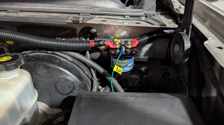
I decided to keep using 0-gauge wire and began wiring to connect the secondary battery in parallel with the starter battery. I also wanted to keep the second battery isolated from the starter battery when the engine is off. To do this, I installed a Stinger 500 A relay in line with the positive wire that goes from the starter battery to the second battery. This relay opens only when a 12V ignition source is present. When the engine is running, the second battery charges; when it's off, the second battery is disconnected from the starter battery.
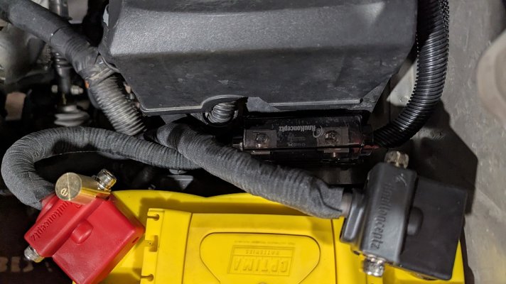
I installed another inline fuse near the second battery. There was not an ideal place to install the fuse, so I fabricated a bracket out of 1/4" ABS that I mounted to a spot between the fuse box and the second battery, and used the battery tray bolts to hold it. I also wanted to install a fuse on the line to the second battery near the starter battery, so there is protection at both batteries.
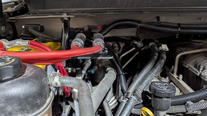
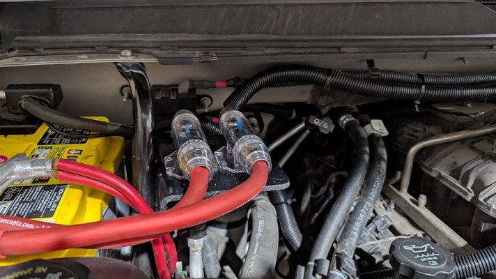
With two large ANL fuses near the starter battery, I needed to mount them so the lines wouldn't hang. I fabricated a bracket out of 1/4" ABS plastic and mounted it to the bar that goes from the firewall to the starter battery tray, and then mounted the fuse holders to it. I decided to use two separate fuse holders instead of a distribution block, keeping them separate.
For the second battery negative post to ground, I used 0-gauge wire and ran it to the bracket holding the alternator.
For the batteries, I chose Optima Yellow-Top AGM, since they are deep-cycle. I am using the same one for the starter battery.
With the second battery installed, I tested the system. I confirmed that the second battery charged while the engine was running, and that the amperage increased when the two batteries were connected. With the engine off, the second battery showed a reduction in amperage as expected, confirming the relay is isolating it from the primary. Once again, I let the truck sit for about a week to verify that this new system isn't draining the batteries. All looked good.
After all this, I went ahead with installing accessories on the second battery, including a new switch controller from Diode Dynamics (D-Switch). All accessories are working as expected, both on and off.
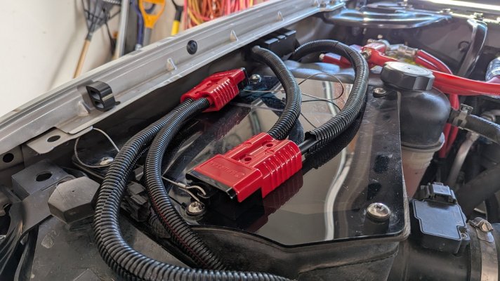
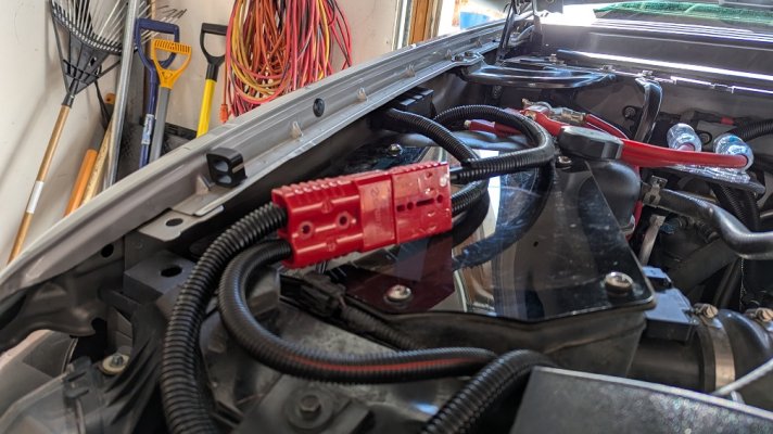
I did keep the winch cables connected to the starter battery. This decision is primarily because the winch wiring runs from the passenger side, and it did not make sense to route it to the second battery. However, I installed quick-disconnects on the winch battery wires so the winch is only connected when I plan to use it. Doing the quick disconnect also prevents any mischievous person from connecting to my winch's control solenoid, which is located near the winch, when I am not around, and the battery is disconnected in case of an accident. The connectors sit easily on top of my Volant air box, out of the way near the fender, and I can quickly connect them when I need to use the winch. I decided to use quick-connects because there was no good place to install a mechanical switch, which would have been ideal.
Anyway, this is my solution for upgrading the electrical system and adding a dual battery. There is more than one way to do this upgrade, so I am not saying mine is the way to go for you. But I am sharing so you can learn from my experience that may help to design your system.
Parts I used:
KnuKoncepts Ultimate Battery Terminal
KnuKonceptz In-Line Waterproof ANL Fuse Holder
KnuKonceptz 1/0 Kolossus Power Wire
Stinger 500 A Relay
Optima Yellow Top 48H6
Mechman 250 A 8302250
Spurtar Battery Quick Connects
Here is a video link where I walk through everything I discussed above.
One of the first upgrades I made to the electrical system was to replace the OEM 500W 5-7-blade radiator fans with a 700W 7-9 setup. I do a lot of towing, and my rig has a lift with heavy armor, so the engine was always running a bit too hot under load to my liking. Upgrading to bigger fans that are used in the heavy-duty option was the next logical step - I already have the transmission cooler.
With the new fans and fan motors, my OEM 160A alternator was doing OK, but when I turned on my accessory lights (pods and light bar), I did notice a significant drawdown, and the alternator seemed to be working harder. The alternator was the original, with 160K miles on it, so I decided to upgrade to a new, higher-output unit with greater amp capacity and amp limits than my OEM alternator. The unit I decided on is the Mechman 250A 8302250. This MM unit is essentially plug-and-play, requiring only the addition of a 0-gauge supplemental energy supply from the alternator to the battery, with all other OEM wiring left as is. I initially challenged the idea of leaving all OEM wiring in place and adding only the 0-gauge from the alt to the battery, but after a lengthy discussion with an engineer at Mechman, he walked me through the electrical engineering and convinced me it was sound and the way to go. I added a 300A inline fuse to this wire near the battery for protection. The engineer also suggested upgrading the ground from the starter battery's negative terminal to the engine block, using 0-gauge wire since I already had 0-gauge to the alternator, but said this was optional. I decided to upgrade this ground wire since I am already upgrading to a higher-output unit and want to reduce the electrical system's resistance back to the alternator.
After completing this part of the installation, I tested the system and confirmed good charging (~14.5 V). I also tested parasitic draw and confirmed the amp draw was below 50 mA with the engine off (this test was done after everything in the electrical system went to sleep). I let the truck sit for a week, and as expected, everything started and looked good. With the new system in place and the engine running, I turned on my fans (using my Autel MK900) and my accessory lights. The new alternator is handling this load well, and the drawdown is minimal compared to my OEM alternator.
My next step in the project was to move my accessories off the starter battery (pods, lightbar, winch) to a secondary battery. I am planning to add other accessories, and I did not want to keep adding to the starter battery. I want to keep the starter battery for starting the truck and running the OEM system, without the risk of accessories draining it and leaving me stranded. The downside of having a second battery is the added weight, but to me, it's worth it since my vehicle is being heavily modified. I am not planning to do audio upgrades, but I am planning to add more lights and possibly run a refrigerator.
I decided to keep using 0-gauge wire and began wiring to connect the secondary battery in parallel with the starter battery. I also wanted to keep the second battery isolated from the starter battery when the engine is off. To do this, I installed a Stinger 500 A relay in line with the positive wire that goes from the starter battery to the second battery. This relay opens only when a 12V ignition source is present. When the engine is running, the second battery charges; when it's off, the second battery is disconnected from the starter battery.
I installed another inline fuse near the second battery. There was not an ideal place to install the fuse, so I fabricated a bracket out of 1/4" ABS that I mounted to a spot between the fuse box and the second battery, and used the battery tray bolts to hold it. I also wanted to install a fuse on the line to the second battery near the starter battery, so there is protection at both batteries.
With two large ANL fuses near the starter battery, I needed to mount them so the lines wouldn't hang. I fabricated a bracket out of 1/4" ABS plastic and mounted it to the bar that goes from the firewall to the starter battery tray, and then mounted the fuse holders to it. I decided to use two separate fuse holders instead of a distribution block, keeping them separate.
For the second battery negative post to ground, I used 0-gauge wire and ran it to the bracket holding the alternator.
For the batteries, I chose Optima Yellow-Top AGM, since they are deep-cycle. I am using the same one for the starter battery.
With the second battery installed, I tested the system. I confirmed that the second battery charged while the engine was running, and that the amperage increased when the two batteries were connected. With the engine off, the second battery showed a reduction in amperage as expected, confirming the relay is isolating it from the primary. Once again, I let the truck sit for about a week to verify that this new system isn't draining the batteries. All looked good.
After all this, I went ahead with installing accessories on the second battery, including a new switch controller from Diode Dynamics (D-Switch). All accessories are working as expected, both on and off.
I did keep the winch cables connected to the starter battery. This decision is primarily because the winch wiring runs from the passenger side, and it did not make sense to route it to the second battery. However, I installed quick-disconnects on the winch battery wires so the winch is only connected when I plan to use it. Doing the quick disconnect also prevents any mischievous person from connecting to my winch's control solenoid, which is located near the winch, when I am not around, and the battery is disconnected in case of an accident. The connectors sit easily on top of my Volant air box, out of the way near the fender, and I can quickly connect them when I need to use the winch. I decided to use quick-connects because there was no good place to install a mechanical switch, which would have been ideal.
Anyway, this is my solution for upgrading the electrical system and adding a dual battery. There is more than one way to do this upgrade, so I am not saying mine is the way to go for you. But I am sharing so you can learn from my experience that may help to design your system.
Parts I used:
KnuKoncepts Ultimate Battery Terminal
KnuKonceptz In-Line Waterproof ANL Fuse Holder
KnuKonceptz 1/0 Kolossus Power Wire
Stinger 500 A Relay
Optima Yellow Top 48H6
Mechman 250 A 8302250
Spurtar Battery Quick Connects
Here is a video link where I walk through everything I discussed above.
Attachments
-
 PXL_20260207_224742716.MP.jpg338.3 KB · Views: 22
 -
 PXL_20260207_224749423.MP.jpg269.2 KB · Views: 13
 -
 PXL_20260207_224753240.MP.jpg285.8 KB · Views: 21
 -
 PXL_20260207_224813220.MP.jpg328.7 KB · Views: 22
 -
 PXL_20260207_225313431.MP.jpg311.4 KB · Views: 17
 -
 PXL_20260207_225317584.MP.jpg295.5 KB · Views: 12
 -
 PXL_20260214_212349705.MP.jpg305.1 KB · Views: 24
 -
 PXL_20260214_212424521.MP.jpg291.7 KB · Views: 21
Last edited: