
Magnaride Compressor Wont Run After Air Leaks Out

Disclaimer: Links on this page pointing to Amazon, eBay and other sites may include affiliate code. If you click them and make a purchase, we may earn a small commission.

Boydzz

TYF Newbie
Joined
May 26, 2021
Posts
6
Reaction score
4
Hello all - great forum here.

Vehicle in question is a 2012 Escalade Platinum AWD with Magneride Package (Z95). OEM Pump and shocks all around. No stored codes.

The issue is the compressor won't refill the bags to maintain the ~20psi of pressure in them. The compressor starts up fine every morning as the bags fully deflate overnight. At morning start-up, the compressor runs momentarily and fills to about ~15-20PSI. I am aware of a...smallish(?) leak on the right rear shock. Soapy water confirm the bag is leaking where it's clamped to the body. I'm planning to replace it with OEM prior to the summer's tow season. Left rear looks good and was replaced 4 years ago.

I have an Otofix scanner that runs Autel software. I can get get access to the suspension control module, perform tests and run the "bump stop" calibration. BTW the bump stop calibration has not fixed my problem.

Last summer I noticed the rear of the vehicle sagging while towing. A key cycle would cause the compressor to run and re-level, but as the system leaked down, the compressor wouldn't restart. This activity is occurring still. System works great at start up, but won't run again until restarted.

I'm leaning towards either a bad ride height sensor, or as others have mentioned here, a faulty vent solenoid valve, or something in the pump (It's old, crusty, and a bit noisy.

Ride Height sensor:
Does anyone know what the nominal value should be?

I've seen a YouTube video of a 2018(?) where as soon as the level "sagged" to from 1.99V to 2.0V the compressor would start up. Here's the url:
.


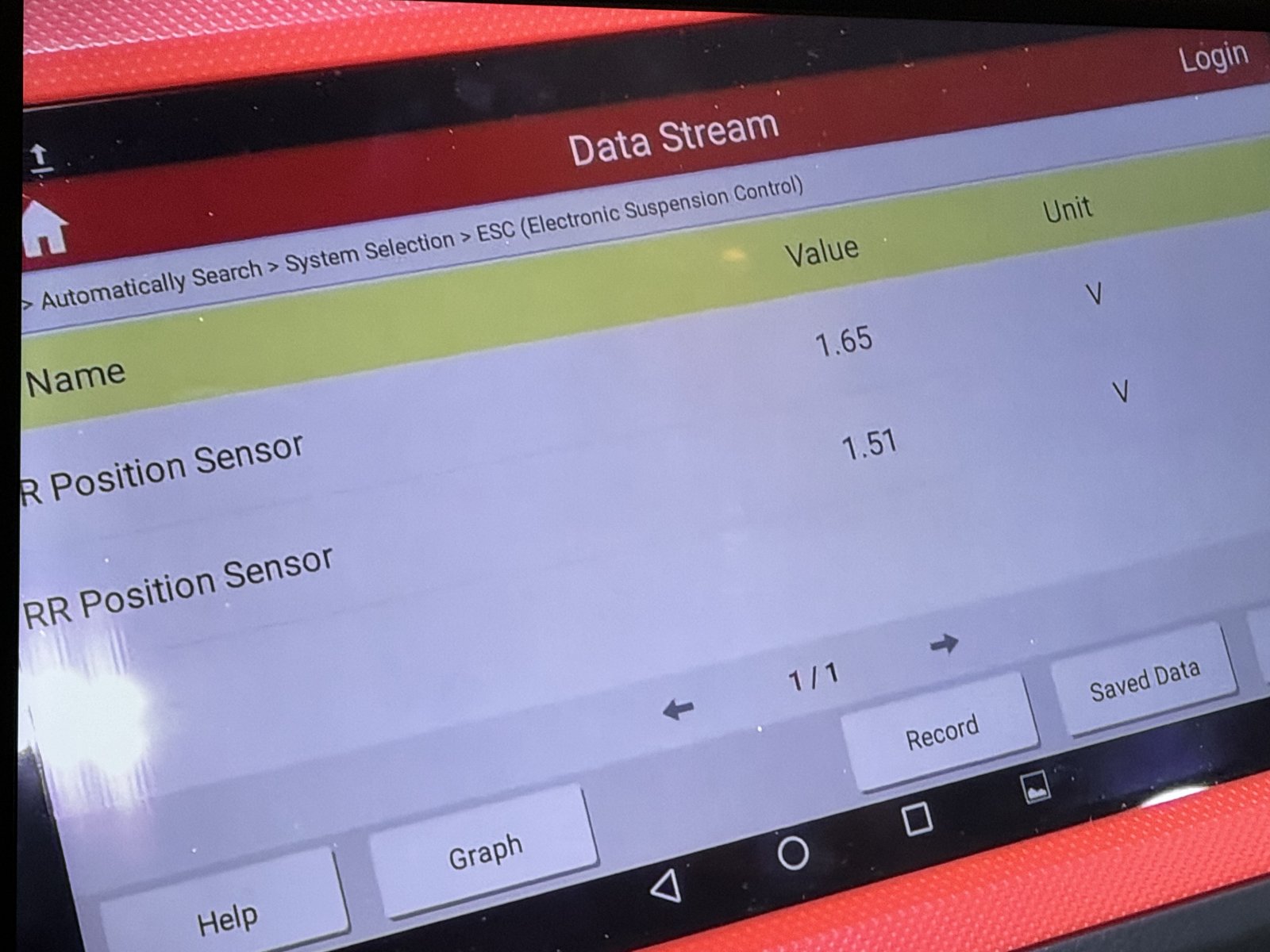
In another video of a NNBS I captured this screen shot, showing both sensors around 1.6V.
IMG_0587.jpeg


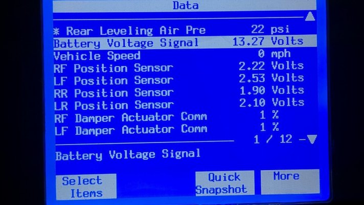
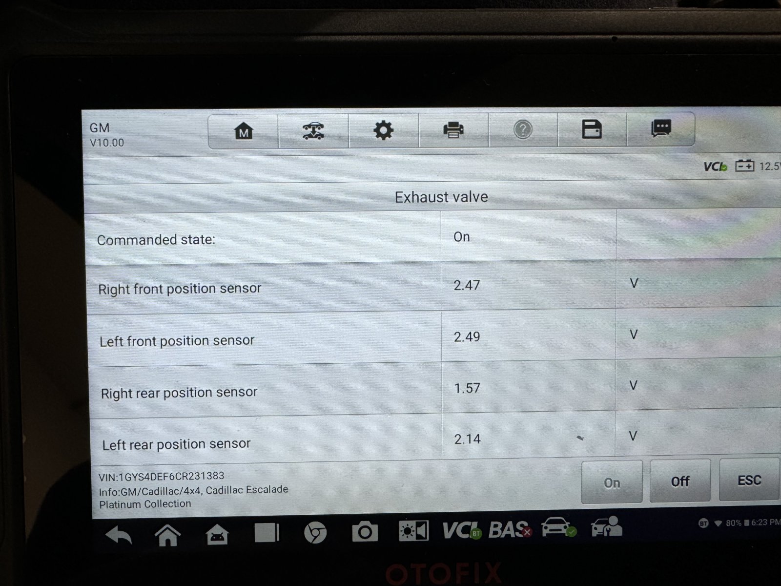
My sensors are in this image. Left Rear @ 2.14, Right Rear @ 1.57. This is flat in the garage.
IMG_0589.jpeg


I have manually disconnected and manipulated the right rear sensor and can get the compressor to turn on. I can't recall if I did that with the left rear.

Edit: Here's a video of the sensors in action as I manually activate the compressor. Note that vent solenoid auto opens after turning off the compressor.

We took a trip today and I took the scan to to monitor the ride height sensors and system pressure. Sensor function looked perfectly normal. For example going around a corner one sensor would extend and the other would contract. The dampening control for left and right rear shocks was mirroring as well. Meaning one side wasn't acting different than the other. Air pressure leaked down from about 20 psi to 3 psi in about 15 minutes drive time...slowish leak.

This is a lot of info, but still comes down to someone with a better understanding of the system...what triggers the system to re-activate as the air leaks out?
 
Last edited:
wjburken

Elite Member
Supporting Member
Joined
Dec 26, 2017
Posts
10,315
Reaction score
29,545
Location
Eastern Iowa
Personally, I’d get new shocks that don’t leak and a new compressor and see what happens. The shocks are obviously at the end of their life if one is leaking and your compressor is likely there as well, especially if it’s the original compressor.
 

Joseph Garcia

Elite Member
Supporting Member
Joined
Aug 2, 2018
Posts
10,521
Reaction score
15,268
Welcome to the Forum from NH.

Lots of knowledgeable folks here who freely share their knowledge, experiences, and perspectives. Knowledge is power.

I hope that you will become a participating member in the Forum's discussions.

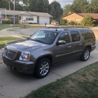
Pics of the truck, please.

You are already receiving sage advice from the knowledgeable folks on this Forum. As @wjburken suggested above, get that leaky shock replaced, and you will in all probability resolve your issue.

ALSO, can you provide me with information on the 'bump stop' calibration? I've search all over for a long time trying to find information on this calibration procedure, but never found anything specific and helpful.
 

Geotrash

Dave
Supporting Member
Joined
Feb 16, 2018
Posts
7,849
Reaction score
20,428
Location
Richmond, VA
Welcome to the Forum from NH.

Lots of knowledgeable folks here who freely share their knowledge, experiences, and perspectives. Knowledge is power.

I hope that you will become a participating member in the Forum's discussions.

Pics of the truck, please.

You are already receiving sage advice from the knowledgeable folks on this Forum. As @wjburken suggested above, get that leaky shock replaced, and you will in all probability resolve your issue.

ALSO, can you provide me with information on the 'bump stop' calibration? I've search all over for a long time trying to find information on this calibration procedure, but never found anything specific and helpful.
As far as I know, it's specific to the Z95 suspension. Here's a cut from Alldata:

1707195148488.png
 

Geotrash

Dave
Supporting Member
Joined
Feb 16, 2018
Posts
7,849
Reaction score
20,428
Location
Richmond, VA
Hello all - great forum here.

Vehicle in question is a 2012 Escalade Platinum AWD with Magneride Package (Z95). OEM Pump and shocks all around. No stored codes.

The issue is the compressor won't refill the bags to maintain the ~20psi of pressure in them. The compressor starts up fine every morning as the bags fully deflate overnight. At morning start-up, the compressor runs momentarily and fills to about ~15-20PSI. I am aware of a...smallish(?) leak on the right rear shock. Soapy water confirm the bag is leaking where it's clamped to the body. I'm planning to replace it with OEM prior to the summer's tow season. Left rear looks good and was replaced 4 years ago.

I have an Otofix scanner that runs Autel software. I can get get access to the suspension control module, perform tests and run the "bump stop" calibration. BTW the bump stop calibration has not fixed my problem.

Last summer I noticed the rear of the vehicle sagging while towing. A key cycle would cause the compressor to run and re-level, but as the system leaked down, the compressor wouldn't restart. This activity is occurring still. System works great at start up, but won't run again until restarted.

I'm leaning towards either a bad ride height sensor, or as others have mentioned here, a faulty vent solenoid valve, or something in the pump (It's old, crusty, and a bit noisy.

Ride Height sensor:
Does anyone know what the nominal value should be?

I've seen a YouTube video of a 2018(?) where as soon as the level "sagged" to from 1.99V to 2.0V the compressor would start up. Here's the url:
.


In another video of a NNBS I captured this screen shot, showing both sensors around 1.6V.View attachment 420693


My sensors are in this image. Left Rear @ 2.14, Right Rear @ 1.57. This is flat in the garage.View attachment 420694

I have manually disconnected and manipulated the right rear sensor and can get the compressor to turn on. I can't recall if I did that with the left rear.

Edit: Here's a video of the sensors in action as I manually activate the compressor. Note that vent solenoid auto opens after turning off the compressor.

We took a trip today and I took the scan to to monitor the ride height sensors and system pressure. Sensor function looked perfectly normal. For example going around a corner one sensor would extend and the other would contract. The dampening control for left and right rear shocks was mirroring as well. Meaning one side wasn't acting different than the other. Air pressure leaked down from about 20 psi to 3 psi in about 15 minutes drive time...slowish leak.

This is a lot of info, but still comes down to someone with a better understanding of the system...what triggers the system to re-activate as the air leaks out?
Here's the full diagnostic from Alldata. Well worth the price of subscription, in my view:

The Automatic Level Control (ALC) System uses the electronic suspension control module (ESCM), level sensors, compressor, and exhaust valve to increase or decrease air pressure in the system to control trim height. Battery voltage is supplied to the exhaust valve and compressor relay. The ESCM controls the ground circuits that activate the exhaust valve and compressor relay which maintain trim height based on the level sensor input voltage.


Circuit/System Verification

Engine running, command the compressor relay ON and OFF with a scan tool. Listen for the compressor running or relay clicks.

Circuit/System Testing

  1. Ignition OFF, disconnect the ALC relay.
  2. Ignition ON, verify that a test lamp does not illuminate between the relay connector control circuit terminal 86 and ground.
¤If the test lamp illuminates, test the control circuit for a short to voltage.
  1. Verify that a test lamp illuminates between the relay connector B+ circuit terminal 85 and ground.
¤If the test lamp does not illuminate, test the B+ circuit for a short to ground or an open/high resistance. If the circuit tests normal and the ESC/ALC EXH fuse is open, test the relay coil B+ circuit for a short to ground. If all circuits test normal, test or replace the ELC relay.
  1. Verify that a test lamp illuminates between the relay connector B+ circuit terminal 30 and ground.
¤If the test lamp does not illuminate, test the B+ circuit for a short to ground or an open/high resistance. If the circuit tests normal and the ALC/COMP fuse is open, test the compressor control circuit for a short to ground. If all circuits test normal, test or replace the ALC compressor.
  1. Disconnect the harness connector at the air compressor.
  2. Test for less than 2 ohms between the ALC compressor ground circuit terminal G and ground.
¤If greater than the specified value, test the ground circuit for an open/high resistance.
  1. Connect the harness connector at the ALC compressor.
  2. Connect a 40A fused jumper wire between the relay connector B+ circuit terminal 30 and the control circuit terminal 87. Verify the ALC compressor is activated.
¤If the ALC compressor does not activate, test the control circuit for an open/high resistance. If the circuit tests normal, test or replace the ALC compressor.
  1. Connect a test lamp between the relay connector B+ circuit terminal 85 and the control circuit terminal 86.
  2. Engine running, command the ALC compressor relay ON and OFF with a scan tool. The test lamp should turn ON and OFF when changing between the commanded states.
¤If the test lamp is always ON, test the control circuit for a short to ground. If the circuit tests normal, replace the ESCM.
¤If the test lamp is always OFF, test the control circuit for a short to voltage or an open/high resistance. If the circuit tests normal, replace the ESCM.
  1. Test the ELC relay.
¤If the ELC relay fails the component test, replace the relay.
  1. Ignition OFF, disconnect the harness connector at the ALC compressor.
  2. Ignition ON, verify that a test lamp illuminates between the ALC compressor connector B+ circuit terminal B and ground.
¤If the test lamp does not illuminate, test the B+ circuit for a short to ground or an open/high resistance. If the circuit tests normal and the ESC/ALC EXH fuse is open, test or replace the ALC compressor.
  1. Connect a test lamp between the ALC compressor connector control circuit terminal C and the B+ circuit terminal B.
  2. Engine running, command the exhaust valve solenoid ON and OFF with a scan tool. The test lamp should turn ON and OFF when changing between the commanded states.
¤If the test lamp is always ON, test the control circuit for a short to ground. If the circuit tests normal, replace the ESCM.
¤If the test lamp is always OFF, test the control circuit for an open/high resistance. If the circuit tests normal, replace the ESCM.
  1. If all circuits test normal, test or replace the ALC compressor.
Component Testing
Relay Test


  1. Ignition OFF, disconnect the relay.
  2. Test for 50-200 ohm between terminals 85 and 86.
¤If the resistance is not within the specified range, replace the relay.
  1. Test for infinite resistance between the following terminals:
  • 30 and 86
  • 30 and 87
  • 30 and 85
  • 85 and 87
¤If not the specified value, replace the relay.
  1. Install a 20 amp fused jumper wire between relay terminal 85 and 12 volts. Install a jumper wire between relay terminal 86 and ground. Test for less than 2.0 ohm between terminals 30 and 87.
¤If greater than the specified range, replace the relay.
Repair Instructions

Perform the Diagnostic Repair Verification See: A L L Diagnostic Trouble Codes ( DTC )\Testing and Inspection\Verification Tests after completing the diagnostic procedure.

 
OP
OP
Boydzz

Boydzz

TYF Newbie
Joined
May 26, 2021
Posts
6
Reaction score
4
Here's the full diagnostic from Alldata. Well worth the price of subscription, in my view:

The Automatic Level Control (ALC) System uses the electronic suspension control module (ESCM), level sensors, compressor, and exhaust valve to increase or decrease air pressure in the system to control trim height. Battery voltage is supplied to the exhaust valve and compressor relay. The ESCM controls the ground circuits that activate the exhaust valve and compressor relay which maintain trim height based on the level sensor input voltage.


Circuit/System Verification

Engine running, command the compressor relay ON and OFF with a scan tool. Listen for the compressor running or relay clicks.

Circuit/System Testing

  1. Ignition OFF, disconnect the ALC relay.
  2. Ignition ON, verify that a test lamp does not illuminate between the relay connector control circuit terminal 86 and ground.
¤If the test lamp illuminates, test the control circuit for a short to voltage.
  1. Verify that a test lamp illuminates between the relay connector B+ circuit terminal 85 and ground.
¤If the test lamp does not illuminate, test the B+ circuit for a short to ground or an open/high resistance. If the circuit tests normal and the ESC/ALC EXH fuse is open, test the relay coil B+ circuit for a short to ground. If all circuits test normal, test or replace the ELC relay.
  1. Verify that a test lamp illuminates between the relay connector B+ circuit terminal 30 and ground.
¤If the test lamp does not illuminate, test the B+ circuit for a short to ground or an open/high resistance. If the circuit tests normal and the ALC/COMP fuse is open, test the compressor control circuit for a short to ground. If all circuits test normal, test or replace the ALC compressor.
  1. Disconnect the harness connector at the air compressor.
  2. Test for less than 2 ohms between the ALC compressor ground circuit terminal G and ground.
¤If greater than the specified value, test the ground circuit for an open/high resistance.
  1. Connect the harness connector at the ALC compressor.
  2. Connect a 40A fused jumper wire between the relay connector B+ circuit terminal 30 and the control circuit terminal 87. Verify the ALC compressor is activated.
¤If the ALC compressor does not activate, test the control circuit for an open/high resistance. If the circuit tests normal, test or replace the ALC compressor.
  1. Connect a test lamp between the relay connector B+ circuit terminal 85 and the control circuit terminal 86.
  2. Engine running, command the ALC compressor relay ON and OFF with a scan tool. The test lamp should turn ON and OFF when changing between the commanded states.
¤If the test lamp is always ON, test the control circuit for a short to ground. If the circuit tests normal, replace the ESCM.
¤If the test lamp is always OFF, test the control circuit for a short to voltage or an open/high resistance. If the circuit tests normal, replace the ESCM.
  1. Test the ELC relay.
¤If the ELC relay fails the component test, replace the relay.
  1. Ignition OFF, disconnect the harness connector at the ALC compressor.
  2. Ignition ON, verify that a test lamp illuminates between the ALC compressor connector B+ circuit terminal B and ground.
¤If the test lamp does not illuminate, test the B+ circuit for a short to ground or an open/high resistance. If the circuit tests normal and the ESC/ALC EXH fuse is open, test or replace the ALC compressor.
  1. Connect a test lamp between the ALC compressor connector control circuit terminal C and the B+ circuit terminal B.
  2. Engine running, command the exhaust valve solenoid ON and OFF with a scan tool. The test lamp should turn ON and OFF when changing between the commanded states.
¤If the test lamp is always ON, test the control circuit for a short to ground. If the circuit tests normal, replace the ESCM.
¤If the test lamp is always OFF, test the control circuit for an open/high resistance. If the circuit tests normal, replace the ESCM.
  1. If all circuits test normal, test or replace the ALC compressor.
Component Testing
Relay Test


  1. Ignition OFF, disconnect the relay.
  2. Test for 50-200 ohm between terminals 85 and 86.
¤If the resistance is not within the specified range, replace the relay.
  1. Test for infinite resistance between the following terminals:
  • 30 and 86
  • 30 and 87
  • 30 and 85
  • 85 and 87
¤If not the specified value, replace the relay.
  1. Install a 20 amp fused jumper wire between relay terminal 85 and 12 volts. Install a jumper wire between relay terminal 86 and ground. Test for less than 2.0 ohm between terminals 30 and 87.
¤If greater than the specified range, replace the relay.
Repair Instructions

Perform the Diagnostic Repair Verification See: A L L Diagnostic Trouble Codes ( DTC )\Testing and Inspection\Verification Tests after completing the diagnostic procedure.

Thank you so much for this info. I will need to digest it in more detail, but what I've pulled initially is there was no mention of a ride height sensor voltage level that triggers the pump to run. It does however mention "performing the Bumpstop and ALC Trimset recalibration procedures". My scan tool only offers the Bumpstop procedure, So I'm wondering if the lack of the ALC procedure is part of my issue.

The system was working great prior to last summer. I have since acquired the scan tool and performed the Bumpstop procedure, but can't get the system to run to keep pressure in the bags, which makes me think one of the ride height sensors is preventing this from happening.

I need to perform more troubleshooting activities...I will load up the back and see if the system comes on. My belief is that it will.

thanks again!
 

Joseph Garcia

Elite Member
Supporting Member
Joined
Aug 2, 2018
Posts
10,521
Reaction score
15,268
Here's the full diagnostic from Alldata. Well worth the price of subscription, in my view:

The Automatic Level Control (ALC) System uses the electronic suspension control module (ESCM), level sensors, compressor, and exhaust valve to increase or decrease air pressure in the system to control trim height. Battery voltage is supplied to the exhaust valve and compressor relay. The ESCM controls the ground circuits that activate the exhaust valve and compressor relay which maintain trim height based on the level sensor input voltage.


Circuit/System Verification

Engine running, command the compressor relay ON and OFF with a scan tool. Listen for the compressor running or relay clicks.

Circuit/System Testing

  1. Ignition OFF, disconnect the ALC relay.
  2. Ignition ON, verify that a test lamp does not illuminate between the relay connector control circuit terminal 86 and ground.
¤If the test lamp illuminates, test the control circuit for a short to voltage.
  1. Verify that a test lamp illuminates between the relay connector B+ circuit terminal 85 and ground.
¤If the test lamp does not illuminate, test the B+ circuit for a short to ground or an open/high resistance. If the circuit tests normal and the ESC/ALC EXH fuse is open, test the relay coil B+ circuit for a short to ground. If all circuits test normal, test or replace the ELC relay.
  1. Verify that a test lamp illuminates between the relay connector B+ circuit terminal 30 and ground.
¤If the test lamp does not illuminate, test the B+ circuit for a short to ground or an open/high resistance. If the circuit tests normal and the ALC/COMP fuse is open, test the compressor control circuit for a short to ground. If all circuits test normal, test or replace the ALC compressor.
  1. Disconnect the harness connector at the air compressor.
  2. Test for less than 2 ohms between the ALC compressor ground circuit terminal G and ground.
¤If greater than the specified value, test the ground circuit for an open/high resistance.
  1. Connect the harness connector at the ALC compressor.
  2. Connect a 40A fused jumper wire between the relay connector B+ circuit terminal 30 and the control circuit terminal 87. Verify the ALC compressor is activated.
¤If the ALC compressor does not activate, test the control circuit for an open/high resistance. If the circuit tests normal, test or replace the ALC compressor.
  1. Connect a test lamp between the relay connector B+ circuit terminal 85 and the control circuit terminal 86.
  2. Engine running, command the ALC compressor relay ON and OFF with a scan tool. The test lamp should turn ON and OFF when changing between the commanded states.
¤If the test lamp is always ON, test the control circuit for a short to ground. If the circuit tests normal, replace the ESCM.
¤If the test lamp is always OFF, test the control circuit for a short to voltage or an open/high resistance. If the circuit tests normal, replace the ESCM.
  1. Test the ELC relay.
¤If the ELC relay fails the component test, replace the relay.
  1. Ignition OFF, disconnect the harness connector at the ALC compressor.
  2. Ignition ON, verify that a test lamp illuminates between the ALC compressor connector B+ circuit terminal B and ground.
¤If the test lamp does not illuminate, test the B+ circuit for a short to ground or an open/high resistance. If the circuit tests normal and the ESC/ALC EXH fuse is open, test or replace the ALC compressor.
  1. Connect a test lamp between the ALC compressor connector control circuit terminal C and the B+ circuit terminal B.
  2. Engine running, command the exhaust valve solenoid ON and OFF with a scan tool. The test lamp should turn ON and OFF when changing between the commanded states.
¤If the test lamp is always ON, test the control circuit for a short to ground. If the circuit tests normal, replace the ESCM.
¤If the test lamp is always OFF, test the control circuit for an open/high resistance. If the circuit tests normal, replace the ESCM.
  1. If all circuits test normal, test or replace the ALC compressor.
Component Testing
Relay Test


  1. Ignition OFF, disconnect the relay.
  2. Test for 50-200 ohm between terminals 85 and 86.
¤If the resistance is not within the specified range, replace the relay.
  1. Test for infinite resistance between the following terminals:
  • 30 and 86
  • 30 and 87
  • 30 and 85
  • 85 and 87
¤If not the specified value, replace the relay.
  1. Install a 20 amp fused jumper wire between relay terminal 85 and 12 volts. Install a jumper wire between relay terminal 86 and ground. Test for less than 2.0 ohm between terminals 30 and 87.
¤If greater than the specified range, replace the relay.
Repair Instructions

Perform the Diagnostic Repair Verification See: A L L Diagnostic Trouble Codes ( DTC )\Testing and Inspection\Verification Tests after completing the diagnostic procedure.

Thank you for posting this. This appears to be a troubleshooting guide procedure for the ALC function, which I am already familiar with. What I cannot find is specific information for "suspension bumpstop procedure".

Thoughts?
 

Geotrash

Dave
Supporting Member
Joined
Feb 16, 2018
Posts
7,849
Reaction score
20,428
Location
Richmond, VA
Thank you for posting this. This appears to be a troubleshooting guide procedure for the ALC function, which I am already familiar with. What I cannot find is specific information for "suspension bumpstop procedure".

Thoughts?
I agree with you, Joseph that it’s inconclusive the way it’s written. One way to interpret it is that bumpstop and ALC are two different procedures, but then we are directed to a step that accomplishes both somehow. So I still don’t know.
 

Geotrash

Dave
Supporting Member
Joined
Feb 16, 2018
Posts
7,849
Reaction score
20,428
Location
Richmond, VA
Thank you so much for this info. I will need to digest it in more detail, but what I've pulled initially is there was no mention of a ride height sensor voltage level that triggers the pump to run. It does however mention "performing the Bumpstop and ALC Trimset recalibration procedures". My scan tool only offers the Bumpstop procedure, So I'm wondering if the lack of the ALC procedure is part of my issue.

The system was working great prior to last summer. I have since acquired the scan tool and performed the Bumpstop procedure, but can't get the system to run to keep pressure in the bags, which makes me think one of the ride height sensors is preventing this from happening.

I need to perform more troubleshooting activities...I will load up the back and see if the system comes on. My belief is that it will.

thanks again!
It’s really hard to tell from the way the instructions are written, as I said to Joseph just above. They may well be one and the same.

One thing I am sure of though, is that if either ride height sensor is telling the computer that the suspension is already at a certain level, it’s impossible to trigger the compressor to come on even using the compressor test function in the GM tech 2 tool. I know because I’ve tried. The solution is to run the calibration program with a scan tool. Since that’s not working in your case, I’m wondering if you have either an erroneous ride height sensor, or the mounting itself has been tweaked somehow. There is a voltage differential between yours if I’m reading your comments right, but I don’t know what the threshold is.
 
OP
OP
Boydzz

Boydzz

TYF Newbie
Joined
May 26, 2021
Posts
6
Reaction score
4
Dave,

Good info. In my case I CAN get the compressor to run using my scan tool. I have run it up to about 100 PSI. Remember, every day the vehicle starts with 0 pressure in the system, and then only runs up to 15-20 PSI as a result of the vehicle starting (compressor test cycle).

To me, the system acts like it thinks it at the correct level even with 0 psi...otherwise it should re-start the compressor at some point when the initial ~20 PSI leaks outs. This further confirms that I need to load up the vehicle with something other than one or two people and see if I can get the compressor to kick on.

To answer your question, yes my ride height sensors are shown in one of the images above. On level ground after the key-on compressor test they are as follows:
Right Front: 2.47V
Left Front: 2.49V
Right Rear: 1.57V
Left Rear: 2.54V

I can get the compressor to come on by manually manipulating the right rear ride height sensor (disconnecting the link and moving it and holding it for a ~10 seconds). I haven't tried this with the LH rear one.
 

Geotrash

Dave
Supporting Member
Joined
Feb 16, 2018
Posts
7,849
Reaction score
20,428
Location
Richmond, VA
Dave,

Good info. In my case I CAN get the compressor to run using my scan tool. I have run it up to about 100 PSI. Remember, every day the vehicle starts with 0 pressure in the system, and then only runs up to 15-20 PSI as a result of the vehicle starting (compressor test cycle).

To me, the system acts like it thinks it at the correct level even with 0 psi...otherwise it should re-start the compressor at some point when the initial ~20 PSI leaks outs. This further confirms that I need to load up the vehicle with something other than one or two people and see if I can get the compressor to kick on.

To answer your question, yes my ride height sensors are shown in one of the images above. On level ground after the key-on compressor test they are as follows:
Right Front: 2.47V
Left Front: 2.49V
Right Rear: 1.57V
Left Rear: 2.54V

I can get the compressor to come on by manually manipulating the right rear ride height sensor (disconnecting the link and moving it and holding it for a ~10 seconds). I haven't tried this with the LH rear one.
Happy to help. Got it. Yeah, my vote goes to that right rear sensor being off - either electronically or physically.
 

j91z28d1

Full Access Member
Joined
Feb 28, 2022
Posts
4,655
Reaction score
5,900
I think you should replace the shocks as the first thing..

worry about the compressor 2nd. because even if you get it running you're just going to burn it up from the leak.


I have a feeling your pump issue will fix itself after you get shocks that hold air overnight. I base that on nothing thou lol
 
OP
OP
Boydzz

Boydzz

TYF Newbie
Joined
May 26, 2021
Posts
6
Reaction score
4
Just an update. New GM AC Delco 580-1091 Shocks from Rock Auto delivered. New Dorman Compressor from Amazon delivered. I will be some time before I get these installed, but I will keep this updated.
 
OP
OP
Boydzz

Boydzz

TYF Newbie
Joined
May 26, 2021
Posts
6
Reaction score
4
I'm debating replacing the left rear ride height sensor. Given the bit of info I have been able to pull from the internet (all captured in my first post), it seems a normal ride height sensor reading is about 1.6V. Given my left rear is reading high I'm wondering if it's creating any issues. Here's a couple data points I pulled re-watching my video.
Screenshot 2024-02-19 at 7.59.38 PM.png


Anyone think that the LH rear sensor could be an issue here? Data seems consistent, just the left hand sensor is skewed higher.
 

petethepug

Michael
Joined
May 4, 2016
Posts
3,790
Reaction score
4,359
Location
SoCal
You may be on to something. It’s new territory for me though. Glad you found the z95 rears @ R/A. Just got the front for our 09 Esky from R/A too.

You’ll need to know the factory went to a new strut # 19420992, from the old z95 MagRide strut #19353951 or you’ll never find em.
 

Doubeleive

Wes
Supporting Member
Joined
Nov 7, 2017
Posts
30,698
Reaction score
48,335
Location
Stockton, Ca.
I'm debating replacing the left rear ride height sensor. Given the bit of info I have been able to pull from the internet (all captured in my first post), it seems a normal ride height sensor reading is about 1.6V. Given my left rear is reading high I'm wondering if it's creating any issues. Here's a couple data points I pulled re-watching my video.View attachment 421842

Anyone think that the LH rear sensor could be an issue here? Data seems consistent, just the left hand sensor is skewed higher.
my own synopsis from experiencing pretty much the same thing is that the system simply will not re-inflate on it's own when it has leaked down and without a key cycle.
yet if it is working normally it will self-inflate/deflate when adding/removing a load on the rear.
I had a slow leak in a shcok and after around 10 minutes it would leak down and the rear end would get squirrely which was how I discovered I had a leak, still held a small amount of air but not fully inflated.
It could very be made that way on purpose so the pump is not kicking on everytime you hit a corner/swerve and instead relies on stabiltrac
also had a slow leak in the relief valve of a pump before, same result
and had another pump with a funky air pressure sensor that thing would maybe inflate to 14 psi or 120 and anything in between

even after messing with it a lot I haven't really looked into what triggers the pump when adding a load (when everything is working normal), is it air pressure? or ride height data?
if it is air pressure feedback then that might explain why it will not self-reinflate after a leak.
 

j91z28d1

Full Access Member
Joined
Feb 28, 2022
Posts
4,655
Reaction score
5,900
as complex as the code in these moduals are today. wouldn't supise me if it looks at everything from air pressure change like you said, if the air pressure is dropping and the hight sensor goes down, it probably knows it doesn't need to run the pump to death trying to overcome a leak. thing probably logs if the hatch was opened and if the fuel gauge increased. so much data is available on the bus these days, it's up to the programer how complicated he wants to get.

for the ride sensor that doesn't agree. can you adjust the rod till it matches the other one?
 
OP
OP
Boydzz

Boydzz

TYF Newbie
Joined
May 26, 2021
Posts
6
Reaction score
4
I went ahead and sourced a left rear ride height sensor from a bone yard in South Carolina off eBay today. It was about $50 shipped, which is about 40% of what a brand new one goes for. I couldn't find much online about these sensors having a history of failing, so I'm hoping it's operational. This will be last resort, but I haven't seen many on ebay, and this set popped up on Friday. I sent the seller a message offering a slightly reduced price for both, but it went unanswered. The RH rear sold, so I went ahead and bought the left hand.

I'm not sure when I will get to working on this. I need it in working order by June. I will come back and update here when I have news.
 

j91z28d1

Full Access Member
Joined
Feb 28, 2022
Posts
4,655
Reaction score
5,900
I had the tech 2 out last night and remembered to check the suspension voltage on mine.. this is a 2011gmc

PXL_20240222_013415282.jpg


compressor kicks on and off as normal. in fact the last day I notched it coming in a few times while driving not just the start test. probably has a leak.

I have new oem shocks just not installed yet. I need to get on that.
 

Forum statistics

Threads
138,039
Posts
1,997,648
Members
102,975
Latest member
jkhuntzinger
Back
Top