P0332, Knock Sensor Low Voltage

Disclaimer: Links on this page pointing to Amazon, eBay and other sites may include affiliate code. If you click them and make a purchase, we may earn a small commission.

chriskat01

TYF Newbie
Joined
Oct 11, 2022
Posts
17
Reaction score
30
My first post, I have this issue and am looking for assistance. I have this code, so far I have replaced both knock sensors. First time with Advance Auto parts, including the pigtail. Second time with AC Delco sensors and pigtail. Both times the code reset within a day or two. I've checked the wires and can't find anything obvious wrong, they have zero ohms end to end and I can't make them short to ground. I replace the ECM. Still the code reset within a day or two. I'm thinking of cutting the wires at both connectors and splicing in new wire from end to end. Any other ideas?

Thanks,
Jeff
 

OR VietVet

GMT800 2005 Tahoe Z71
Navy Supporting Member
Joined
Oct 8, 2014
Posts
23,937
Reaction score
44,668
Location
Willamette Valley
Welcome to the forum. It certainly would help to know the vehicle info. I am guessing a 2000 to 2006, but that is just a guess. When you say which code, which code(s) are we talking about. You have already shot the "parts cannon" at it.
 

Joseph Garcia

Elite Member
Supporting Member
Joined
Aug 2, 2018
Posts
10,549
Reaction score
15,313
Welcome to the Forum from NH.

Lots of knowledgeable folks here who freely share their knowledge, experiences, and perspectives. Knowledge is power.

I hope that you will become a participating member in the Forum's discussions.

More detailed info, please.
 

nick0789

Full Access Member
Joined
Aug 22, 2017
Posts
209
Reaction score
177
I do not know you skill level / knowledge base so I apologize if any of my ideas come across as dumb to you:

- do you still have the original harness to re-install, to confirm whether the harness is the culprit? I don’t suspect it to be the harness, personally, but it’s probably worth performing a sanity check on it
- what did you torque the knock sensors down to?
- have you swapped knock sensors (front to back, back to front) to see if P0332 populates or if you get P0327 instead?
- are the threads clean on the engine itself?

When I replaced my knock sensors earlier this year (as part of the intake manifold gasket job) I swore I torqued everything down but my rear knock sensor was only snug tight … not that “snug tight” is much different than what’s specified but still. And of course I pulled the plug and cracked the ceramic top so I had to replace it anyways.

Hopefully you get it figured out soon!
 
OP
OP
C

chriskat01

TYF Newbie
Joined
Oct 11, 2022
Posts
17
Reaction score
30
Thanks to everyone.

I do not have the harness any longer but I have replaced it twice now, of course that doesn't mean they were both bad but three (including the original) harnesses have produced the same code.

I also have not swapped the sensors front to back, I thought about that but it's a lot of work and two new sensors have produced the same code. Probably worth a try.

I torqued the knock sensors to 15 ft lbs, actually 180 inch lbs because my ft lb torque wrench won't go below 30.

Does anyone know if there is any "interruption" in the wire from the connector at the intake manifold to the connector at the ECM? I'm wondering if that wire could be broken or intermittent somewhere along the way but I'm not sure where that could be.

Thanks again.
 

rockola1971

Full Access Member
Joined
Dec 29, 2016
Posts
2,862
Reaction score
4,085
Location
Indiana (formerly IL)
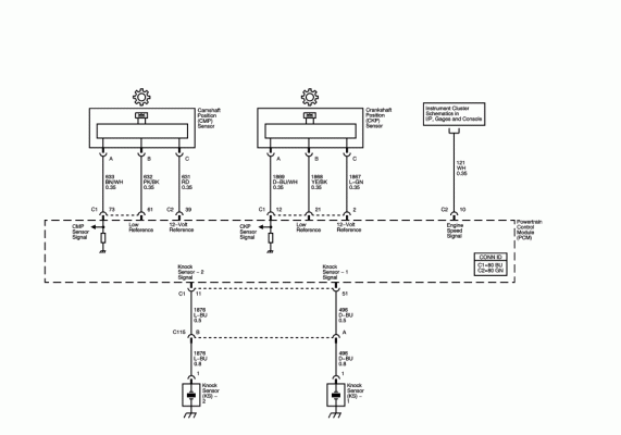
P0332 denotes Knock sensor bank 2. Bank 2 wire is Light Blue. (Bank 1 should be dark blue). With engine running what kind of voltage reading are you getting off of both the bank 1 and 2 knock sensors? (Dont disconnect harness anywhere while taking reading).
 

Attachments

  • engine sensors.gif
    engine sensors.gif
    34.9 KB · Views: 141
OP
OP
C

chriskat01

TYF Newbie
Joined
Oct 11, 2022
Posts
17
Reaction score
30
P0332 denotes Knock sensor bank 2. Bank 2 wire is Light Blue. (Bank 1 should be dark blue). With engine running what kind of voltage reading are you getting off of both the bank 1 and 2 knock sensors? (Dont disconnect harness anywhere while taking reading).
I don't know the voltage I'm getting. I'll have to check. Any idea what the voltage is supposed to be?
 
OP
OP
C

chriskat01

TYF Newbie
Joined
Oct 11, 2022
Posts
17
Reaction score
30
By the way, my understanding is that the resistance of the knock sensor to ground should be 100K ohms nominally. These are both measuring 98.7K ohms.
 

rockola1971

Full Access Member
Joined
Dec 29, 2016
Posts
2,862
Reaction score
4,085
Location
Indiana (formerly IL)
By the way, my understanding is that the resistance of the knock sensor to ground should be 100K ohms nominally. These are both measuring 98.7K ohms.
You should be measuring 93k-110k for a GM knock sensor. The voltage is a tricky situation. On most sensors you will have a power feed voltage and then a sensor output voltage and both of those voltages are DC. This is not true in the case of a knock sensor. A knock sensor only outputs a voltage when their is a knock condition going on in the engine. Here is the even trickier part that a DIY mechanic needs to know and remember when working on the knock sensor(s) circuit. The knock sensor is a piezoelectric accelerometer which is basically an old school microphone that uses a crystal that produces AC VOLTAGE when sound is acted upon it! So when you check the output of your knock sensor you have to either cause a knock (by tapping the block or head with a hammer) or the engine has to be running and has a knock condition (AKA Spark Knock). You wont see any DC output from the knock sensor. ONLY AC OUTPUT! During testing using the old hammer on the block test the knock sensor will produce around 1.3-1.5 VAC. Measure sensor out (wire that goes to PCM) using red lead of multimeter and black lead of multimeter on engine block (ground) or knock sensor body if it is out of the engine.

If both knock sensors test good for resistance (measuring at knock sensor harness) and both pass the sensor output voltage test then I would test wire(s) going to PCM. I believe it is a straight shot to the PCM connector from the connection to the knock sensor harness according to the schematic I attached earlier.

REMEMBER: Volatge coming out of knock sensor is AC VOLTAGE so put your meter on AC Volts! (NOT DC).
 
OP
OP
C

chriskat01

TYF Newbie
Joined
Oct 11, 2022
Posts
17
Reaction score
30
I thought I already posted this but apparently not. I understand that the resistance is supposed to be 100k ohms nominally. Both of these read 98.7K ohms.
 
OP
OP
C

chriskat01

TYF Newbie
Joined
Oct 11, 2022
Posts
17
Reaction score
30
You should be measuring 93k-110k for a GM knock sensor. The voltage is a tricky situation. On most sensors you will have a power feed voltage and then a sensor output voltage and both of those voltages are DC. This is not true in the case of a knock sensor. A knock sensor only outputs a voltage when their is a knock condition going on in the engine. Here is the even trickier part that a DIY mechanic needs to know and remember when working on the knock sensor(s) circuit. The knock sensor is a piezoelectric accelerometer which is basically an old school microphone that uses a crystal that produces AC VOLTAGE when sound is acted upon it! So when you check the output of your knock sensor you have to either cause a knock (by tapping the block or head with a hammer) or the engine has to be running and has a knock condition (AKA Spark Knock). You wont see any DC output from the knock sensor. ONLY AC OUTPUT! During testing using the old hammer on the block test the knock sensor will produce around 1.3-1.5 VAC. Measure sensor out (wire that goes to PCM) using red lead of multimeter and black lead of multimeter on engine block (ground) or knock sensor body if it is out of the engine.

If both knock sensors test good for resistance (measuring at knock sensor harness) and both pass the sensor output voltage test then I would test wire(s) going to PCM. I believe it is a straight shot to the PCM connector from the connection to the knock sensor harness according to the schematic I attached earlier.

REMEMBER: Volatge coming out of knock sensor is AC VOLTAGE so put your meter on AC Volts! (NOT DC)
Thanks very much, I knew a lot of that but for sure not the voltage that should be measured. I suppose in order to see this voltage I'll need to set my meter on peak hold?

One other question. I've already tested the wires best I can and they seem to be a dead short end to end and I can't make them ground to the chassis by moving the harness. What would everyone think of putting a new wire in place from the "main" connector up on the intake manifold down to the computer connector? I would solder both ends and maybe use an outdoor type shrink tubing to seal the joint.

Not sure what else it could be. Assuming the voltage from the knock sensors is actually good.

If it is a bad knock sensor this will be replacement number 3. That would make me not happy.
 

Fless

Staff member
Moderator
Joined
Apr 2, 2017
Posts
16,647
Reaction score
34,452
Location
People's Republic of Colorado
Unless you've already done this, I would recommend a very careful inspection of pin fitment, and cleaning (e.g., DeOxit or similar) of the pins on the ECM connector, before doing a wire bypass. This in addition to the voltage tests indicated earlier.
 

rockola1971

Full Access Member
Joined
Dec 29, 2016
Posts
2,862
Reaction score
4,085
Location
Indiana (formerly IL)
Thanks very much, I knew a lot of that but for sure not the voltage that should be measured. I suppose in order to see this voltage I'll need to set my meter on peak hold?

One other question. I've already tested the wires best I can and they seem to be a dead short end to end and I can't make them ground to the chassis by moving the harness. What would everyone think of putting a new wire in place from the "main" connector up on the intake manifold down to the computer connector? I would solder both ends and maybe use an outdoor type shrink tubing to seal the joint.

Not sure what else it could be. Assuming the voltage from the knock sensors is actually good.

If it is a bad knock sensor this will be replacement number 3. That would make me not happy.
No sense in fixing what aint broken. I suggest popping the PCM connector off the PCM and inspecting for corrosion. Green/Blue nasty things growing on the pin(s). During the hammer test on a knock sensor you should see an immediate jump of the AC voltage. You wont need a peak hold set on your meter. Just tap the hammer head on the valley cover plate and that should be enough to trigger the knock sensors. As Fless mentioned check for pushed pins (female and male) in the connectors too.

You can also depin the knock sensor harness and swap the 2 knock sensors wires around in the plug and see if the trouble code moves to the other bank. If it does then you have a bad knock sensor.
 

RAMurphy

Bob
Military
Joined
Oct 5, 2011
Posts
1,450
Reaction score
4,649
Location
S. Maryland
You should be measuring 93k-110k for a GM knock sensor. The voltage is a tricky situation. On most sensors you will have a power feed voltage and then a sensor output voltage and both of those voltages are DC. This is not true in the case of a knock sensor. A knock sensor only outputs a voltage when their is a knock condition going on in the engine. Here is the even trickier part that a DIY mechanic needs to know and remember when working on the knock sensor(s) circuit. The knock sensor is a piezoelectric accelerometer which is basically an old school microphone that uses a crystal that produces AC VOLTAGE when sound is acted upon it! So when you check the output of your knock sensor you have to either cause a knock (by tapping the block or head with a hammer) or the engine has to be running and has a knock condition (AKA Spark Knock). You wont see any DC output from the knock sensor. ONLY AC OUTPUT! During testing using the old hammer on the block test the knock sensor will produce around 1.3-1.5 VAC. Measure sensor out (wire that goes to PCM) using red lead of multimeter and black lead of multimeter on engine block (ground) or knock sensor body if it is out of the engine.

If both knock sensors test good for resistance (measuring at knock sensor harness) and both pass the sensor output voltage test then I would test wire(s) going to PCM. I believe it is a straight shot to the PCM connector from the connection to the knock sensor harness according to the schematic I attached earlier.

REMEMBER: Volatge coming out of knock sensor is AC VOLTAGE so put your meter on AC Volts! (NOT DC).
Awesome post. I learned something today (therefore a good day). Always amazed with the talent and knowledge on this forum.
 
Last edited:
OP
OP
C

chriskat01

TYF Newbie
Joined
Oct 11, 2022
Posts
17
Reaction score
30
Sorry I haven't replied in a while, been working on some plumbing issues in the house. I've spray both connectors with cleaner today and repinned the connector to swap bank 1 and bank 2. We'll see what code gets set now, if any.
 
OP
OP
C

chriskat01

TYF Newbie
Joined
Oct 11, 2022
Posts
17
Reaction score
30
Okay, so set a new code on the ten mile trip to Lowes and back. Now it's P0327 which, based on the internet, is low voltage knock sensor bank 1. My reader doesn't give the bank for this code but it did for P0322. So I guess I have another bad knock sensor, this would be two bad out of the box and I happened to put the bad ones in the same spot. I'm thinking about buying two more attaching them somewhere they aren't intended to be but is easy to get to and hook them up, run for a few days to make sure I dont' get any codes before I change them, again.

Thoughts?
 

rockola1971

Full Access Member
Joined
Dec 29, 2016
Posts
2,862
Reaction score
4,085
Location
Indiana (formerly IL)
Okay, so set a new code on the ten mile trip to Lowes and back. Now it's P0327 which, based on the internet, is low voltage knock sensor bank 1. My reader doesn't give the bank for this code but it did for P0322. So I guess I have another bad knock sensor, this would be two bad out of the box and I happened to put the bad ones in the same spot. I'm thinking about buying two more attaching them somewhere they aren't intended to be but is easy to get to and hook them up, run for a few days to make sure I dont' get any codes before I change them, again.

Thoughts?
The problem moving to the other knock sensor wire shows it is indeed a bad knock sensor. Dont forget to swap your depinned wires back to their original place so you can keep track what a new code is pointing at later in life if another knock sensor were to fail. You can hookup a knock sensor but not install it. The only problem is that if you get engine knock then the sensors likely will not detect it and then your spark timing wont be retarded to stop the knock condition. Engine damage can happen then.
The sensors can be bench tested right out of the box on a workbench to verify a good part too.
 
Last edited:

Forum statistics

Threads
138,095
Posts
1,998,912
Members
103,022
Latest member
scottd
Back
Top