
Transmission codes after rebuild

Disclaimer: Links on this page pointing to Amazon, eBay and other sites may include affiliate code. If you click them and make a purchase, we may earn a small commission.

Mickey_7106

Full Access Member
Joined
Oct 22, 2018
Posts
485
Reaction score
316
Location
Bay Area
Hello,
My brother had his transmission rebuilt and its throwing a few codes. The tech came out and is saying the tranny isn't receiving any electrical current. Does anyone know of a way to test this theory? Do i turn the key to On and probe all the pins to verify this?

Thanks

2001 tahoe 2wd.

P0740 Tcc circuit open
P0753 shift solenoid A electrical
P1810 TFP Valve Position Switch Circuit 3
P1860 Tcc pmw solenoid circuit electrical
P0713 Transmission fluid temp sensor circuit high input

 

Just Fishing

Can't fix stupid
Joined
Aug 30, 2020
Posts
4,544
Reaction score
10,223
Location
Utah
probably going to need to first check the plug on the side of the transmission, make sure it's in there.
then since this probably a 4l60e, pull the transmission pan to ensure everything is actually plugged in.
if you have a tech2, then you can also check each circuit to see if it's registering an open circuit (not plugged in).
 
OP
OP
Mickey_7106

Mickey_7106

Full Access Member
Joined
Oct 22, 2018
Posts
485
Reaction score
316
Location
Bay Area
Thanks yall. I just looked up the manual for possible fuses to look for. Does anyone know if the pinout changed throughout the years for the 4l60e? Getting different info online for what each pin is. I just ordered the vcxnano. Been eyeing it for a while. Hopefully it can help with this problem.
 

rockola1971

Full Access Member
Joined
Dec 29, 2016
Posts
2,862
Reaction score
4,085
Location
Indiana (formerly IL)
Thanks yall. I just looked up the manual for possible fuses to look for. Does anyone know if the pinout changed throughout the years for the 4l60e? Getting different info online for what each pin is. I just ordered the vcxnano. Been eyeing it for a while. Hopefully it can help with this problem.
Did you even verify that the WIring harness is plugged in to the tranny?

How exactly do you intend to get the various gear signals out of the PCM to check for correct signal on each wire to the tranny while the vehicle is in park sitting in your garage or driveway?
 
OP
OP
Mickey_7106

Mickey_7106

Full Access Member
Joined
Oct 22, 2018
Posts
485
Reaction score
316
Location
Bay Area
Did you even verify that the WIring harness is plugged in to the tranny?

How exactly do you intend to get the various gear signals out of the PCM to check for correct signal on each wire to the tranny while the vehicle is in park sitting in your garage or driveway?
Everything is plugged in. Not sure how I'm going to do it. That's why I'm here asking for help. I'm hoping the vcxnano helps with diagnosing. Only useful info i have from the mechanic is that there's no power going to the tranny. But in the meantime i want to see if i can test individual pins for voltage
 

rockola1971

Full Access Member
Joined
Dec 29, 2016
Posts
2,862
Reaction score
4,085
Location
Indiana (formerly IL)
Everything is plugged in. Not sure how I'm going to do it. That's why I'm here asking for help. I'm hoping the vcxnano helps with diagnosing. Only useful info i have from the mechanic is that there's no power going to the tranny. But in the meantime i want to see if i can test individual pins for voltage
I think you are missing the point. The only way for you to check the voltages is to have the vehicle setup in the correct configuration to output those voltages (from the PCM). And in order to do that you would either have to be rolling down the road or sitting on a vehicle lift in gear. Because of the quantity of codes and misisng voltages I would have to suspect that the problem is common to the whole tranny wiring harness/control system. And those common items are:
(1) Harness is unplugged at tranny or PCM side OR all of the wires in the tranny (which connect to that harness via the plug) were not attached to the various solenoids and pressure switch on the valve body.
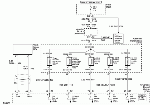
(2) You have lost ground at the PCM which is G103 in the attached schematic.
(3) You have lost 12v + which is provided by IGN Fuse 10A and is fed down the pink wire to the tranny plug. This is an easy check with a voltmeter and can be verified quickly.
(4) Your tranny wiring harness has been completely cut through at some place or the pink wire is broken.

I would check the igntion fuse first and verify its not blown since its the easiest to check. Then check for 12v+ on the tranny PLUG pink wire. Let us know what you find on these 2 checks and we can torubleshoot from there.
One key thing to remember on MOST vehicle is that 12v+ is usually fed constantly to solenoids and relays. It is the ground that is switched on and off via the PCM, etc. If you have a look at the attached schematic you will see the switches for the various tranny solenoids are in the PCM. Those switches are actually transistors which are used to switch the circuits on and off. This is called a ground seeking system as far as controls go since the 12v is fed constantly but the ground is not.
 

Attachments

  • Tranny wiring.gif
    Tranny wiring.gif
    70.8 KB · Views: 30
OP
OP
Mickey_7106

Mickey_7106

Full Access Member
Joined
Oct 22, 2018
Posts
485
Reaction score
316
Location
Bay Area
I think you are missing the point. The only way for you to check the voltages is to have the vehicle setup in the correct configuration to output those voltages (from the PCM). And in order to do that you would either have to be rolling down the road or sitting on a vehicle lift in gear. Because of the quantity of codes and misisng voltages I would have to suspect that the problem is common to the whole tranny wiring harness/control system. And those common items are:
(1) Harness is unplugged at tranny or PCM side OR all of the wires in the tranny (which connect to that harness via the plug) were not attached to the various solenoids and pressure switch on the valve body.
(2) You have lost ground at the PCM which is G103 in the attached schematic.
(3) You have lost 12v + which is provided by IGN Fuse 10A and is fed down the pink wire to the tranny plug. This is an easy check with a voltmeter and can be verified quickly.
(4) Your tranny wiring harness has been completely cut through at some place or the pink wire is broken.

I would check the igntion fuse first and verify its not blown since its the easiest to check. Then check for 12v+ on the tranny PLUG pink wire. Let us know what you find on these 2 checks and we can torubleshoot from there.
One key thing to remember on MOST vehicle is that 12v+ is usually fed constantly to solenoids and relays. It is the ground that is switched on and off via the PCM, etc. If you have a look at the attached schematic you will see the switches for the various tranny solenoids are in the PCM. Those switches are actually transistors which are used to switch the circuits on and off. This is called a ground seeking system as far as controls go since the 12v is fed constantly but the ground is not.
Thanks, i really appreciate all the help. I'll be checking the truck tomorrow. will update with my findings
 
OP
OP
Mickey_7106

Mickey_7106

Full Access Member
Joined
Oct 22, 2018
Posts
485
Reaction score
316
Location
Bay Area
I think you are missing the point. The only way for you to check the voltages is to have the vehicle setup in the correct configuration to output those voltages (from the PCM). And in order to do that you would either have to be rolling down the road or sitting on a vehicle lift in gear. Because of the quantity of codes and misisng voltages I would have to suspect that the problem is common to the whole tranny wiring harness/control system. And those common items are:
(1) Harness is unplugged at tranny or PCM side OR all of the wires in the tranny (which connect to that harness via the plug) were not attached to the various solenoids and pressure switch on the valve body.
(2) You have lost ground at the PCM which is G103 in the attached schematic.
(3) You have lost 12v + which is provided by IGN Fuse 10A and is fed down the pink wire to the tranny plug. This is an easy check with a voltmeter and can be verified quickly.
(4) Your tranny wiring harness has been completely cut through at some place or the pink wire is broken.

I would check the igntion fuse first and verify its not blown since its the easiest to check. Then check for 12v+ on the tranny PLUG pink wire. Let us know what you find on these 2 checks and we can torubleshoot from there.
One key thing to remember on MOST vehicle is that 12v+ is usually fed constantly to solenoids and relays. It is the ground that is switched on and off via the PCM, etc. If you have a look at the attached schematic you will see the switches for the various tranny solenoids are in the PCM. Those switches are actually transistors which are used to switch the circuits on and off. This is called a ground seeking system as far as controls go since the 12v is fed constantly but the ground is not.
There's 12v coming from the pink wire at the round plug on the tranny. Checked fuses 15, 27, 30, 46, 49, and 53 under the hood and 5, 14 and 14 on the driver side dash. All good there. Spent most of the day trying to figure out how to get the vcx nano to communicate
 
OP
OP
Mickey_7106

Mickey_7106

Full Access Member
Joined
Oct 22, 2018
Posts
485
Reaction score
316
Location
Bay Area
Also check continuity of the battery to ground which i believe is G103 you mentioned. All good there too.
 

rockola1971

Full Access Member
Joined
Dec 29, 2016
Posts
2,862
Reaction score
4,085
Location
Indiana (formerly IL)
Next up I would Pull C1 and C2 connectors off the PCM (Disconnect your neg or pos at battery first) and ohm out the solenoids in the tranny via the c1 and c2 connectors. This will verify the wires are internally attached to the respective solenoids. The pinout is in the above attached schematic directly above the PCM at the very bottom of the schematic. While you are there at the PCM, inspect C1 and C2 connectors for the green crust which is corrosion and clean accordingly with a tooth brush and electrical contact cleaner such as Deoxit.

If all checks good at C1 and C2 then the solenoids, wiring harness from PCM to tranny is good and then I suspect the PCM is bad or possibly needs to be reflashed. This owuld lead me to believe the PCM caused the tranny needing to be rebuilt OR the tranny shop did damage to the PCM because they had something hooked up wrong at the tranny.
 

rockola1971

Full Access Member
Joined
Dec 29, 2016
Posts
2,862
Reaction score
4,085
Location
Indiana (formerly IL)
Also check continuity of the battery to ground which i believe is G103 you mentioned. All good there too.
I dont know your schematic reading and electrical torubleshooting skills so just in case. You will need to pull IGN 0 fuse (10A). Stick a voltmeter on the terminals which the fuse was pulled from and see which one does NOT have 12v+ on it all the time.(Do this test before disconnecting battery) This will be your PINK wire to the top side of each solenoid and you can just stick a meter lead in that terminal for ohming out all solenoids in the tranny since that PINK wire is common to all the solenoids. Then take your other meter lead and stick it on each respecitive PCM plug terminal noted in the schematic for each solenoid. You should not read electrically open (infinite resistance) on any of the solenoid circuits. If you have any questions just ask away!
 

Rocket Man

Mark
Supporting Member
Joined
Dec 25, 2014
Posts
26,679
Reaction score
52,954
Location
Oregon
Not saying it happened, but if they got the harness pinched at the top of the bellhousing where it crosses over it could be causing this. It’s happened before- there’s a couple harness clamps that go on studs at the top of the bellhousing instead of just bolts there. Some shops don’t bother with installing the studs and then attach the harness with nuts in the studs because it’s difficult so they just leave the harness hanging and put bolts in. Then the harness falls down into the gap and the trans is bolted up, pinching the harness. The only way to see up there is to remove the trans mount, let the tail hang down, and then you can shine a light up there and look. This is assuming the shop did the R&R?
 
OP
OP
Mickey_7106

Mickey_7106

Full Access Member
Joined
Oct 22, 2018
Posts
485
Reaction score
316
Location
Bay Area
I dont know your schematic reading and electrical torubleshooting skills so just in case. You will need to pull IGN 0 fuse (10A). Stick a voltmeter on the terminals which the fuse was pulled from and see which one does NOT have 12v+ on it all the time.(Do this test before disconnecting battery) This will be your PINK wire to the top side of each solenoid and you can just stick a meter lead in that terminal for ohming out all solenoids in the tranny since that PINK wire is common to all the solenoids. Then take your other meter lead and stick it on each respecitive PCM plug terminal noted in the schematic for each solenoid. You should not read electrically open (infinite resistance) on any of the solenoid circuits. If you have any questions just ask away!
i do ok with reading schematics. i don't know what a lot of the symbols mean but i can figure out the flow path if that make sense. Also i know how to troubleshoot using a multimeter and have basic knowledge on 12v and 120v electrical systems.
 
OP
OP
Mickey_7106

Mickey_7106

Full Access Member
Joined
Oct 22, 2018
Posts
485
Reaction score
316
Location
Bay Area
Not saying it happened, but if they got the harness pinched at the top of the bellhousing where it crosses over it could be causing this. It’s happened before- there’s a couple harness clamps that go on studs at the top of the bellhousing instead of just bolts there. Some shops don’t bother with installing the studs and then attach the harness with nuts in the studs because it’s difficult so they just leave the harness hanging and put bolts in. Then the harness falls down into the gap and the trans is bolted up, pinching the harness. The only way to see up there is to remove the trans mount, let the tail hang down, and then you can shine a light up there and look. This is assuming the shop did the R&R?
No pinching in this case. i used a bore scope to check a possible loose ground. My brothers did the R&R
 

Rocket Man

Mark
Supporting Member
Joined
Dec 25, 2014
Posts
26,679
Reaction score
52,954
Location
Oregon
Something else I have heard of happening is the potting inside the electrical connector on the side of the trans fails with age and trans fluid gets inside that connector and shorts out the pins where you plug the harness in. That ones fairly easy to inspect by removing the wiring connector and looking inside the cavity on the side of the trans, especially with a borescope. You might just buy a wiring harness for the transmission, drop the pan and replace it also. I had one on hand and was going to replace it, I was having a 2-3 shift solenoid dtc and had already replaced the solenoid so I was fairly certain it was the harness. I ended up finding out from my trans builder that their build didn’t use that solenoid anyway so I just set it to not report that dtc in the tune. The problem is still there but the computer is none the wiser and the trans shifts fine. So the internal harnesses can fail on these- they’re submerged in trans fluid, not sure if that affects them.
 

Just Fishing

Can't fix stupid
Joined
Aug 30, 2020
Posts
4,544
Reaction score
10,223
Location
Utah
Rattling crap off from the top of my head,

If the plugs got plugged into the wrong places, or if the solenoids were faulty, it might cause some of the errors.
Grounds is a big one that could be missed.
Also installing the plug incorrectly or not completely locked in could cause some issues.

If all else fails,
"atsg 4l60e"

Good reads, there is a main repair manual, update manual, and the error code manual.
They also cover wiring and inspection of those solenoids.

Also, each solenoid has its own place, and they do fail.
If one got pulled from a large pile via the rebuilder, that could be a problem.
or if gunk ended up in one of the solenoids when the transmission failed, that's a thing.
Each one should rattle, search YouTube for details covering cleaning and inspection...

If you have a tech 2 (china clone works fine, I paid about $300 for mine), you can view detailed data, see open circuits and activate each module one by one.

That said,
These screams one of these to me,

plug failure (and that's common, look for transmission fluid leaking through the connector).
Issues related to a bad or sloppy install, or didn't hook everything up
Damaged wiring harness. (That could be internal or external to the transmission)
grounding issues (related to installation probably)

This is of course assuming everything worked fine before the rebuild, and that the current issues seen isn't related to why the transmission was rebuilt in the first place.

If a ground issues,
Try a jumper cable from the negative on the battery and connect the lead to the transmission case directly as a test.
 
OP
OP
Mickey_7106

Mickey_7106

Full Access Member
Joined
Oct 22, 2018
Posts
485
Reaction score
316
Location
Bay Area
I dont know your schematic reading and electrical torubleshooting skills so just in case. You will need to pull IGN 0 fuse (10A). Stick a voltmeter on the terminals which the fuse was pulled from and see which one does NOT have 12v+ on it all the time.(Do this test before disconnecting battery) This will be your PINK wire to the top side of each solenoid and you can just stick a meter lead in that terminal for ohming out all solenoids in the tranny since that PINK wire is common to all the solenoids. Then take your other meter lead and stick it on each respecitive PCM plug terminal noted in the schematic for each solenoid. You should not read electrically open (infinite resistance) on any of the solenoid circuits. If you have any questions just ask away!
Per your suggestion, I'm getting 21.5 ohms on C1 pin 79 and no reading on C2 2,42, 47 and 48.
Does that mean the solenoids are not plugged or just bad? I do have some oil coming through the round plug if that makes a difference
20221127143408221.jpg
 

Rocket Man

Mark
Supporting Member
Joined
Dec 25, 2014
Posts
26,679
Reaction score
52,954
Location
Oregon
Per your suggestion, I'm getting 21.5 ohms on C1 pin 79 and no reading on C2 2,42, 47 and 48.
Does that mean the solenoids are not plugged or just bad? I do have some oil coming through the round plug if that makes a difference View attachment 386188
I can’t tell from that pic, but if it’s coming through the center where the pins slide together then yes that’s a problem. A new internal wiring harness will fix that, it comes with that connector.
 

Forum statistics

Threads
138,090
Posts
1,998,675
Members
103,015
Latest member
The Whip
Back
Top