5v ref issue

Disclaimer: Links on this page pointing to Amazon, eBay and other sites may include affiliate code. If you click them and make a purchase, we may earn a small commission.

allisonw79

TYF Newbie
Joined
Mar 14, 2024
Posts
7
Reaction score
2
I have 07 tahoe, it's giving a 5v ref. Backstory: engine oil pressure light kept coming on, replaces oil press sensor, it began making a knocking noise, I replaced engine w crate motor. At times when I would crank it, the starter would spin...turn it off then bake on and it cranks. After engine replacement, it kept doing it so I had starter replaced. I also replaced fuel pump in the event that was causing starter to spin over. Lastly, the stabiltrak light came on., reduced power engine, gas pedal not working. I've checked all wires and replaced cam shaft, crankshaft, ac high pressure, fuel pressure sensor. Still getting 5v ref issue. Crazy thing is I have no rpms when camshaft sensor is plugged in, if I unplug it I have rpms. Pls help.
 

Fless

Staff member
Moderator
Joined
Apr 2, 2017
Posts
16,279
Reaction score
33,637
Location
People's Republic of Colorado
Welcome to TYF from Colorado!

When you say it's giving a 5v ref., where is that measured, on what circuit? Lots of the components and sensors use a 5v reference voltage.
 
OP
OP
A

allisonw79

TYF Newbie
Joined
Mar 14, 2024
Posts
7
Reaction score
2
Welcome to TYF from Colorado!

When you say it's giving a 5v ref., where is that measured, on what circuit? Lots of the components and sensors use a 5v reference voltage.
Well that's the thing...we have a code reader, the sensors as we read each one says (ac high pressure)
5v 1 5.5,
5v 2 5.5
Sensor reading is around 0.231 or 0.265
The code that keeps coming up is p0641 and p0651
 
OP
OP
A

allisonw79

TYF Newbie
Joined
Mar 14, 2024
Posts
7
Reaction score
2
Well that's the thing...we have a code reader, the sensors as we read each one says (ac high pressure)
5v 1 5.5,
5v 2 5.5
Sensor reading is around 0.231 or 0.265
The code that keeps coming up is p0641 and p0651
We are tracking all those sensors
Camshaft
Crankshaft
Fuel pressure
Oil pressure
MAF
MAP
AC High pressure
Accelerate pedal
 

j91z28d1

Full Access Member
Joined
Feb 28, 2022
Posts
4,603
Reaction score
5,863
this is a curious one I've not heard of? seems your 5v output from the ecm is a half volt to high? interesting. I'll attach what I found. I read it as unhook every sensor on line 1 and 2 then test the 5v at the sensor plugs and see if it's still wrong. at that point I'd personally unpin that pin at the ecm and test it there before replacing the ecm. it's so rare that a ecm actually fails and 2 outputs at a time would seem to be more rare.

but good luck. sounds like a lot of digging around under the hood wiring. a shop will probably throw an ecm at it first because that's the least labor for them and most money out of you.
 

Attachments

  • P0641 P0651.jpg
    P0641 P0651.jpg
    266.2 KB · Views: 57
  • P0641 P06510001.jpg
    P0641 P06510001.jpg
    225.6 KB · Views: 59
  • P0641 P06510002.jpg
    P0641 P06510002.jpg
    299.6 KB · Views: 50

mikez71

Full Access Member
Joined
Mar 9, 2023
Posts
3,199
Reaction score
3,952
Am I reading it right, that the starter will self crank after turning off the motor?

That does seem odd that there are no RPMs with the cam sensor disconnected. Definately check the wiring to cam sensor! (sounds like you may have already)

Also, looking at J91z28d1's attachment, it seems like accelerator pedal position can set both of those codes, whereas the other sensors will only set one code.. AC Pressure supposed to be Accelerator position in your scanner? idk
 
Last edited:
OP
OP
A

allisonw79

TYF Newbie
Joined
Mar 14, 2024
Posts
7
Reaction score
2
Out of curiosity when I'm reading the code reader on any given sensor, I check the box for 5v1 and 5v2 and then the specific sensor....the reading displayed should be:
5v1 5v or near that amt
5v2 5v or near that amt
Sensor should be what?
We disagree on the readout for this line item...I say that 0.265 or whatever is OK for the truck being off, my husband says it shld say 5v also.
 

mikez71

Full Access Member
Joined
Mar 9, 2023
Posts
3,199
Reaction score
3,952
5V ref should be 5V. Sensor signal would be a different wire that could be anything (less than 5V ref)
 

j91z28d1

Full Access Member
Joined
Feb 28, 2022
Posts
4,603
Reaction score
5,863
yes, the sensor voltage is going to be less than 5v. that the output the ecm turns into a useful number. it will vary depending on the kinda of sensor thou. like say cam and crank should put out a sign wave of some sort, usually a square wave and the frequency is counted by the ecm.

for the starter I'm taking it you mean the starter electric motor would spin but did not engage the flywheel to turn the engine over. that isn't the most common way they fail, but most likely not part if this issue.


the 5v reference code sounds to me like it's being set because it's reading to high from the ecm, not about what reading is coming back from the sensor. the first thing I would do was test the 5v at the sensor plug under the hood with a volt meter and see if it matches your scanner.

for the rpm not working on when you plug in the cam sensor. is that scanner rpm or dash tach? I hate to just throw parts at it. but that sensor might be bad. I'm not sure of a eazy way to test it without a way to back prob the sensor plug and know what you're looking for.
 

Joseph Garcia

Elite Member
Supporting Member
Joined
Aug 2, 2018
Posts
10,284
Reaction score
14,887
Welcome to the Forum from NH.

Lots of knowledgeable folks here who freely share their knowledge, experiences, and perspectives. Knowledge is power.

I hope that you will become a participating member in the Forum's discussions.

Pics of the truck, please.

You are already receiving clarifying questions from the knowledgeable folks on this Forum.
 
OP
OP
A

allisonw79

TYF Newbie
Joined
Mar 14, 2024
Posts
7
Reaction score
2
yes, the sensor voltage is going to be less than 5v. that the output the ecm turns into a useful number. it will vary depending on the kinda of sensor thou. like say cam and crank should put out a sign wave of some sort, usually a square wave and the frequency is counted by the ecm.

for the starter I'm taking it you mean the starter electric motor would spin but did not engage the flywheel to turn the engine over. that isn't the most common way they fail, but most likely not part if this issue.


the 5v reference code sounds to me like it's being set because it's reading to high from the ecm, not about what reading is coming back from the sensor. the first thing I would do was test the 5v at the sensor plug under the hood with a volt meter and see if it matches your scanner.

for the rpm not working on when you plug in the cam sensor. is that scanner rpm or dash tach? I hate to just throw parts at it. but that sensor might be bad. I'm not sure of a eazy way to test it without a way to back prob the sensor plug and know what you're looking for.
So I spent a few hours starting at the cam sensor following wires back tonecm plug, then following additional wire in the plug pin forward..anyway..it went cam to plug, then green wire from there to throttle, then throttle back to plug then gray wire in that set out to alternator sensor. When I got there, the gray wire has turned green and we tested this plug wire alone back to ecm plug...the beep stopped where the green color started....so I stripped back insulation and found the copper wire had turned green on gray and brown wire....could this cause issues that we are having
 

j91z28d1

Full Access Member
Joined
Feb 28, 2022
Posts
4,603
Reaction score
5,863
hmm well it's definitely not good, you may have saved yourself issues down the road at worst. my stuff says gray is the signal wire from ecm to control alt volt output. it's a pwm square wave and brown is the the return wire to the ecm, uses a pwm signal to tell the ecm how hard it's loading the engine to do what it's being asked to do. helps the ecm keep a stable idle and stuff.

I don't see either of those wires in the 5v ref circuit 1 or 2 thou.

on the cam position sensor the blue wire is your 5v ref 1 wire ecm pin 43. should have 5v there. brown is the sensor ground ecm pin 66 and dark blue/white is the signal wire back.

map sensor grey is the 5v ref 1. pin 43 of the ecm.
sensor ground wire is orange/blk pin 53 at the ecm.


throttle pedal
tan wire is 5v ref 1 ecm pin 36.
pink is sensor ground on ecm pin 23
white/black is 5v ref 2 ecm pin 56. sensor ground is brown ecm pin 30

oil pressure sensor is gray wire 5v ref 1 ecm pin 41.
ground is the black wire at the plug and pin 34

throttle body Grey wire 5v ref 2 ecm pin 3
sensor ground is the tan wire ecm pin 35.

i don't know if any of that is any help. but might give you a place to check for that 5 volts and if you get plus or minus a half volt, it might mean something. if I'm reading it right and that's when it sets the codes you have.

sorry I'm not more help. literally didn't even know a 5v reference code existed
 
OP
OP
A

allisonw79

TYF Newbie
Joined
Mar 14, 2024
Posts
7
Reaction score
2
hmm well it's definitely not good, you may have saved yourself issues down the road at worst. my stuff says gray is the signal wire from ecm to control alt volt output. it's a pwm square wave and brown is the the return wire to the ecm, uses a pwm signal to tell the ecm how hard it's loading the engine to do what it's being asked to do. helps the ecm keep a stable idle and stuff.

I don't see either of those wires in the 5v ref circuit 1 or 2 thou.

on the cam position sensor the blue wire is your 5v ref 1 wire ecm pin 43. should have 5v there. brown is the sensor ground ecm pin 66 and dark blue/white is the signal wire back.

map sensor grey is the 5v ref 1. pin 43 of the ecm.
sensor ground wire is orange/blk pin 53 at the ecm.


throttle pedal
tan wire is 5v ref 1 ecm pin 36.
pink is sensor ground on ecm pin 23
white/black is 5v ref 2 ecm pin 56. sensor ground is brown ecm pin 30

oil pressure sensor is gray wire 5v ref 1 ecm pin 41.
ground is the black wire at the plug and pin 34

throttle body Grey wire 5v ref 2 ecm pin 3
sensor ground is the tan wire ecm pin 35.

i don't know if any of that is any help. but might give you a place to check for that 5 volts and if you get plus or minus a half volt, it might mean something. if I'm reading it right and that's when it sets the codes you have.

sorry I'm not more help. literally didn't even know a 5v reference code existed
It does help another. Also all these are giving 5.5 v for both ref 1 and ref 2....any ideas on what would make it be above normal.
 
OP
OP
A

allisonw79

TYF Newbie
Joined
Mar 14, 2024
Posts
7
Reaction score
2
Let me back up
It does help another. Also all these are giving 5.5 v for both ref 1 and ref 2....any ideas on what would make it be above normal.
Let me back up and ask this...there are 2 plugs to the ecm...so is one plug 5v ref1 and the 2nd plug is 5v ref 2
I guess I'm thinking just to back up to beginning and go back thru it all
 

Doubeleive

Wes
Supporting Member
Joined
Nov 7, 2017
Posts
30,501
Reaction score
47,902
Location
Stockton, Ca.
So I spent a few hours starting at the cam sensor following wires back tonecm plug, then following additional wire in the plug pin forward..anyway..it went cam to plug, then green wire from there to throttle, then throttle back to plug then gray wire in that set out to alternator sensor. When I got there, the gray wire has turned green and we tested this plug wire alone back to ecm plug...the beep stopped where the green color started....so I stripped back insulation and found the copper wire had turned green on gray and brown wire....could this cause issues that we are having
are you saying the actual bare copper wire, turned green, gray, brown? if so then yes the wire is probably bad and should be replaced
one way to tell is to ohm test the wire
 

j91z28d1

Full Access Member
Joined
Feb 28, 2022
Posts
4,603
Reaction score
5,863
Let me back up

Let me back up and ask this...there are 2 plugs to the ecm...so is one plug 5v ref1 and the 2nd plug is 5v ref 2
I guess I'm thinking just to back up to beginning and go back thru it all

*wall of text warning*

I don't know the physical plug to pin numbers on this ecm. they are all labeled differently. Ref 1 and Ref 2 could be in 2 different physical harness to ecm plugs, or the same. it doesn't really matter, it would just be how the engineer that designed the board inside laid it out. the 2 chips that output 5v are probably side by side in there somewhere.

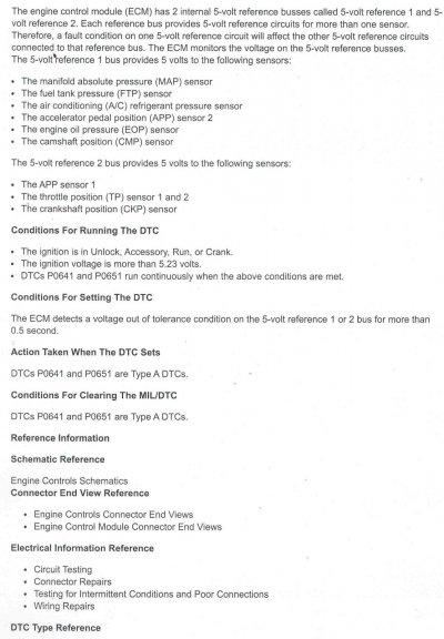
they use 2 different 5v circuits for redundancy for the fly by wire throttle and gas pedal. technically either one of the 2 chips could burn out, lose the 5v and you'd still have throttle control. the old cable throttle only has one position sensor, they needed to add a 2nd since it's possible these could stick open with a lost of signal from a bad sensor.

so we would need a schematic of the ecm itself, which is almost impossible to find and would be pages long, so all I can do it guess from what the troubleshooting software says.
so my take is the ecm has 2 transistors, probably some kinda FET really, but either way. 2 electrical components that output a very steady state sold 5 volts. this is used to power the sensors. the return from the sensors is less than 5v varied by whatever it's designed for. like say for instance your 2.3 volts in the return wire. the ecm will turn that analog 2.3 volts into a digital number. usually 0-255. I don't remember why 255, something to do with 2 digits of hex. (above my pay grade) but left over from when ecm's didn't have a lot of space and computing power so space was kept at a minimum. anyways, off topic. sorry.
that 2.3v needs to be very specific, so much so that the ecm also supplies a sensor ground on a 3rd wire. it could easily just ground to the engine block or something saving time and money. but it can't because you get small voltage drops from a ground like that. it needs a known ground and 5v. so that it knows that 2.3v signal is correct.

so from reading this about your fault codes..

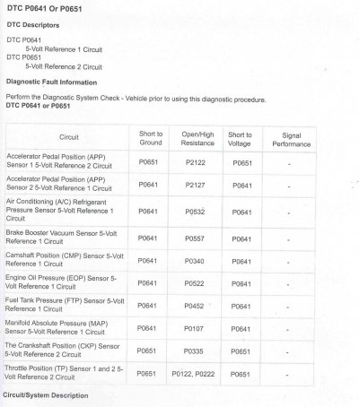
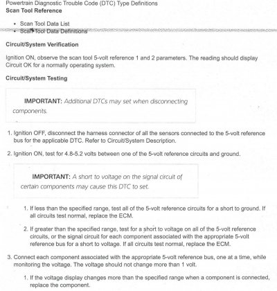
1. Ignition OFF, disconnect the harness connector of all the sensors connected to the 5-volt reference bus
*(bus is what they are calling the circuit. ref 1 is one 5v bus, ref 2 is another 5v bus)* for the applicable DTC. Refer to Circuit/System Description.

2. Ignition ON, test for 4.8-5.2 volts between one of the 5-volt reference circuits and ground.(in the plug, not the engine block, even thou that might be useful info too)

IMPORTANT: A short to voltage on the signal circuit of certain components may cause this DTC to set.

1. If less than the specified range, test all of the 5-volt reference circuits for a short to ground. If all circuits test normal, replace the ECM.

2. If greater than the specified range, test for a short to voltage on all of the 5-volt reference circuits, or the signal circuit for each component associated with the appropriate 5-volt reference bus for a short to voltage. If all circuits test normal, replace the ECM.

3. Connect each component associated with the appropriate 5-volt reference bus, one at a time, while monitoring the voltage. The voltage should not change more than 1 volt.

1. If the voltage display changes more than the specified range when a component is connected, replace the component.

and you saying you're seeing above 5.2v on the 5v ref 1 and Rev 2 circuit. that rules out most of what the trouble shooting expects. it expects the more common low voltage by a sensor shorting internally to ground and dragging the voltage low. but you have high, which is harder cause where is that voltage coming from? either a short to voltage inside the harness or ecm. but it's very odd to me that it's only a few tenths of a volt and both 1 and 2 read the same.

so at this point. I'm not sure what else to check that's easily done. I would hate to say change the ecm like the guide jumps to without exhausting all ideas to test. they are expensive, requiring programed to the truck by a dealer level scanner.


I would make sure you're checking the 5.5v at the sensor plug with a good multi meter, not just going by what the scanner says?
 

petethepug

Michael
Joined
May 4, 2016
Posts
3,788
Reaction score
4,355
Location
SoCal
What type of code scanner are you using? I assume you’re reading directly through your OBD right?

Ever replaced your battery -/+ cables?

Any prior work or diagnostics for on this issue or did it start after other work was performed?
 

Forum statistics

Threads
137,689
Posts
1,989,663
Members
102,689
Latest member
Woned2004
Back
Top