Rockman101
Member
- Joined
- Nov 6, 2023
- Posts
- 30
- Reaction score
- 34
Disclaimer: Links on this page pointing to Amazon, eBay and other sites may include affiliate code. If you click them and make a purchase, we may earn a small commission.
Does the starter solenoid click when you turn the key?
Parameter | Expected Value | Definition |
| Operating Conditions: Ignition ON | ||
| Auto Learn Counter | Varies | This displays Counts. This is the number of times the auto learn procedure was carried out by the TDM. |
| Auto. Learn Timer | Varies | This displays minutes. This is the amount of minutes the TDM took to auto learn. |
| Battery Reconnect | No | The scan tool displays Yes or No. Yes is displayed if the battery was recently reconnected. |
| Fleet Vehicle | No | The scan tool displays Yes or No. Yes is displayed if the vehicle is a fleet vehicle. |
| Fuel Continue | No | The scan tool displays Yes or No. |
| Fuel Disable Ignition Off | Yes | The scan tool displays Yes or No. Yes is displayed if the fuel is disabled during ignition OFF. |
| Fuel Disable Timeout | No | The scan tool displays Yes or No. Yes is displayed if the fuel disable timed out. |
| Ignition Voltage Signal | Present | The scan tool displays Present or Not Present. Present is displayed if there is an ignition voltage signal to the TDM. |
| Immobilization | Inactive | The scan tool displays Active or Inactive. This is the state of the immobilizer system. |
| Immobilizer Programmed | Yes | The scan tool displays Yes or No. This is the state of the immobilizer system programming. |
| Incorrect VIN 1 | No Error | The scan tool displays Unknown, No Error, ECM/PCM, TCM, EBCM, DSCC, TBCM, ESCM, ASCM, BCM, BCM Aux., SDM, PPS, ROS, PIDM, IPC, DIC, HUD, Chime, Radio, Amp., CDX, RSA, DRR, Onstar, HVAC, RCC, DDM, PDM, LRDM, RRDM, LGM, PSDM, MSM, HVSM, RCDLR, SOD, TDM or SCLM. The module displayed has an incorrect VIN programmed into that module. |
| Incorrect VIN 2 | No Error | The scan tool displays Unknown, No Error, ECM/PCM, TCM, EBCM, DSCC, TBCM, ESCM, ASCM, BCM, BCM Aux., SDM, PPS, ROS, PIDM, IPC, DIC, HUD, Chime, Radio, Amp., CDX, RSA, DRR, Onstar, HVAC, RCC, DDM, PDM, LRDM, RRDM, LGM, PSDM, MSM, HVSM, RCDLR, SOD, TDM or SCLM. The module displayed has an incorrect VIN programmed into that module. |
| Incorrect VIN 3 | No Error | The scan tool displays Unknown, No Error, ECM/PCM, TCM, EBCM, DSCC, TBCM, ESCM, ASCM, BCM, BCM Aux., SDM, PPS, ROS, PIDM, IPC, DIC, HUD, Chime, Radio, Amp., CDX, RSA, DRR, Onstar, HVAC, RCC, DDM, PDM, LRDM, RRDM, LGM, PSDM, MSM, HVSM, RCDLR, SOD, TDM or SCLM. The module displayed has an incorrect VIN programmed into that module. |
| Incorrect VIN 4 | No Error | The scan tool displays Unknown, No Error, ECM/PCM, TCM, EBCM, DSCC, TBCM, ESCM, ASCM, BCM, BCM Aux., SDM, PPS, ROS, PIDM, IPC, DIC, HUD, Chime, Radio, Amp., CDX, RSA, DRR, Onstar, HVAC, RCC, DDM, PDM, LRDM, RRDM, LGM, PSDM, MSM, HVSM, RCDLR, SOD, TDM or SCLM. The module displayed has an incorrect VIN programmed into that module. |
| Incorrect VIN 5 | No Error | The scan tool displays Unknown, No Error, ECM/PCM, TCM, EBCM, DSCC, TBCM, ESCM, ASCM, BCM, BCM Aux., SDM, PPS, ROS, PIDM, IPC, DIC, HUD, Chime, Radio, Amp., CDX, RSA, DRR, Onstar, HVAC, RCC, DDM, PDM, LRDM, RRDM, LGM, PSDM, MSM, HVSM, RCDLR, SOD, TDM or SCLM. The module displayed has an incorrect VIN programmed into that module. |
| Incorrect VIN 6 | No Error | The scan tool displays Unknown, No Error, ECM/PCM, TCM, EBCM, DSCC, TBCM, ESCM, ASCM, BCM, BCM Aux., SDM, PPS, ROS, PIDM, IPC, DIC, HUD, Chime, Radio, Amp., CDX, RSA, DRR, Onstar, HVAC, RCC, DDM, PDM, LRDM, RRDM, LGM, PSDM, MSM, HVSM, RCDLR, SOD, TDM or SCLM. The module displayed has an incorrect VIN programmed into that module. |
| Incorrect VIN 7 | No Error | The scan tool displays Unknown, No Error, ECM/PCM, TCM, EBCM, DSCC, TBCM, ESCM, ASCM, BCM, BCM Aux., SDM, PPS, ROS, PIDM, IPC, DIC, HUD, Chime, Radio, Amp., CDX, RSA, DRR, Onstar, HVAC, RCC, DDM, PDM, LRDM, RRDM, LGM, PSDM, MSM, HVSM, RCDLR, SOD, TDM or SCLM. The module displayed has an incorrect VIN programmed into that module. |
| Incorrect VIN 8 | No Error | The scan tool displays Unknown, No Error, ECM/PCM, TCM, EBCM, DSCC, TBCM, ESCM, ASCM, BCM, BCM Aux., SDM, PPS, ROS, PIDM, IPC, DIC, HUD, Chime, Radio, Amp., CDX, RSA, DRR, Onstar, HVAC, RCC, DDM, PDM, LRDM, RRDM, LGM, PSDM, MSM, HVSM, RCDLR, SOD, TDM or SCLM. The module displayed has an incorrect VIN programmed into that module. |
| Incorrect VIN 9 | No Error | The scan tool displays Unknown, No Error, ECM/PCM, TCM, EBCM, DSCC, TBCM, ESCM, ASCM, BCM, BCM Aux., SDM, PPS, ROS, PIDM, IPC, DIC, HUD, Chime, Radio, Amp., CDX, RSA, DRR, Onstar, HVAC, RCC, DDM, PDM, LRDM, RRDM, LGM, PSDM, MSM, HVSM, RCDLR, SOD, TDM or SCLM. The module displayed has an incorrect VIN programmed into that module. |
| Incorrect VIN 10 | No Error | The scan tool displays Unknown, No Error, ECM/PCM, TCM, EBCM, DSCC, TBCM, ESCM, ASCM, BCM, BCM Aux., SDM, PPS, ROS, PIDM, IPC, DIC, HUD, Chime, Radio, Amp., CDX, RSA, DRR, Onstar, HVAC, RCC, DDM, PDM, LRDM, RRDM, LGM, PSDM, MSM, HVSM, RCDLR, SOD, TDM or SCLM. The module displayed has an incorrect VIN programmed into that module. |
| Learn Coded Key | No | The scan tool displays Yes or No. |
| Master Keys Learned | Varies | This displays Counts. This is the number of master keys learned by the TDM. |
| PCM Authentication Status | Valid | The scan tool displays Unknown, Incorrect, Negative or Valid. This is the state of the PCM authentication. |
| PCM Auto. Learn Timer | Inactive | The scan tool displays Active or Inactive. This is the current state of the ECM auto learn timer. |
| PCM Password Learning | Enabled | The scan tool displays Enabled or Disabled. This is the state of the password learning in the ECM. |
| PCM Release Status | Release | The scan tool displays Unknown, Post Release, Pre-Release or Release. This is the release status of the ECM. |
| Power Mode | Run | The scan tool displays Off, Accessory, Run or Crank Request. This is the state of the ignition switch. |
| Powertrain DTC | No | The scan tool displays Yes or No. Yes is displayed if there is a powertrain DTC stored in the ECM or TCM. |
| Previous TDM State | Varies | The scan tool displays Asleep, Wakeup, Normal, Learn Passkey, Tamper, Monitor Key, Fail Pending, Fail Enabled, Lrn Keys Stdby, Learn More Keys, Learn Pending, Auto Learn, Auto. Lrn. Done, No Coded Key, Check Second Key, VIN Check, OnStar, Bypass, Override or VIN Timer. This was the last state of the TDM. |
| Security Code Programmed | No | The scan tool displays Yes or No. Yes is displayed if a security code is programmed. |
| Start Disabled | No | The scan tool displays Yes or No. Yes is displayed if the starter is disabled. |
| Substitution Detection Status | Pass | The scan tool displays Pass or Fail. Pass is displayed if the TDM does not sense a module with incorrect VIN programming. |
| Tamper Status | Inactive | The scan tool displays Active or Inactive. This is the state of the tamper system. |
| TDM State | Varies | The scan tool displays Asleep, Wakeup, Normal, Learn Passkey, Tamper, Monitor Key, Fail Pending, Fail Enabled, Lrn Keys Stdby, Learn More Keys, Learn Pending, Auto Learn, Auto. Lrn. Done, No Coded Key, Check Second Key, VIN Check, OnStar, Bypass, Override, or VIN Timer. This was the last state of the TDM. |
| Telltale Status | Off | The scan tool displays On, Off, Flash or Invalid. This is the state of the security indicator. |
| Theft Problem | No | The scan tool displays Yes or No. Yes is displayed if there is a theft problem. |
| Total Keys Learned | Varies | This displays Counts. This is the number of total keys learned by the TDM. |
| Transponder Key | Present | The scan tool displays Present or Not Present. Present is displayed when a transponder is present. This does not mean that this is a valid or learned transponder, but only that a transponder is present. |
| Valid Key | Yes | The scan tool displays Yes or No. Yes is displayed if a valid key was used as monitored by the TDM. |
| Valid VIN | Yes | The scan tool displays Yes or No. Yes is displayed if the VIN is valid. |
| VIN Learned | Yes | The scan tool displays Yes or No. Yes is displayed if the VIN was learned. |
| VIN Message Received | Yes | The scan tool displays Yes or No. Yes is displayed if the VIN message is received |
Thank you very much!!!! Starter solenoid does not click. So I'll go through the troubleshooting above and report back. It does have a new programmed ECM. But could possibly be the Bcm causing the problem. Im currently troubleshooting the gmlans high and low. But everything seems to be communicating right. Can see all modules on scan tool. Thanks againAnd here is the full list of scan tool parameters from the theft deterrent module. I'm not seeing some of the things on the screen you captured that would tell us what we need to know. For example whether immobilization is active or inactive.
Operating Conditions: Ignition ON Auto Learn Counter This displays Counts. This is the number of times the auto learn procedure was carried out by the TDM. Auto. Learn Timer This displays minutes. This is the amount of minutes the TDM took to auto learn. Battery Reconnect The scan tool displays Yes or No. Yes is displayed if the battery was recently reconnected. Fleet Vehicle The scan tool displays Yes or No. Yes is displayed if the vehicle is a fleet vehicle. Fuel Continue The scan tool displays Yes or No. Fuel Disable Ignition Off The scan tool displays Yes or No. Yes is displayed if the fuel is disabled during ignition OFF. Fuel Disable Timeout The scan tool displays Yes or No. Yes is displayed if the fuel disable timed out. Ignition Voltage Signal The scan tool displays Present or Not Present. Present is displayed if there is an ignition voltage signal to the TDM. Immobilization The scan tool displays Active or Inactive. This is the state of the immobilizer system. Immobilizer Programmed The scan tool displays Yes or No. This is the state of the immobilizer system programming. Incorrect VIN 1 The scan tool displays Unknown, No Error, ECM/PCM, TCM, EBCM, DSCC, TBCM, ESCM, ASCM, BCM, BCM Aux., SDM, PPS, ROS, PIDM, IPC, DIC, HUD, Chime, Radio, Amp., CDX, RSA, DRR, Onstar, HVAC, RCC, DDM, PDM, LRDM, RRDM, LGM, PSDM, MSM, HVSM, RCDLR, SOD, TDM or SCLM. The module displayed has an incorrect VIN programmed into that module. Incorrect VIN 2 The scan tool displays Unknown, No Error, ECM/PCM, TCM, EBCM, DSCC, TBCM, ESCM, ASCM, BCM, BCM Aux., SDM, PPS, ROS, PIDM, IPC, DIC, HUD, Chime, Radio, Amp., CDX, RSA, DRR, Onstar, HVAC, RCC, DDM, PDM, LRDM, RRDM, LGM, PSDM, MSM, HVSM, RCDLR, SOD, TDM or SCLM. The module displayed has an incorrect VIN programmed into that module. Incorrect VIN 3 The scan tool displays Unknown, No Error, ECM/PCM, TCM, EBCM, DSCC, TBCM, ESCM, ASCM, BCM, BCM Aux., SDM, PPS, ROS, PIDM, IPC, DIC, HUD, Chime, Radio, Amp., CDX, RSA, DRR, Onstar, HVAC, RCC, DDM, PDM, LRDM, RRDM, LGM, PSDM, MSM, HVSM, RCDLR, SOD, TDM or SCLM. The module displayed has an incorrect VIN programmed into that module. Incorrect VIN 4 The scan tool displays Unknown, No Error, ECM/PCM, TCM, EBCM, DSCC, TBCM, ESCM, ASCM, BCM, BCM Aux., SDM, PPS, ROS, PIDM, IPC, DIC, HUD, Chime, Radio, Amp., CDX, RSA, DRR, Onstar, HVAC, RCC, DDM, PDM, LRDM, RRDM, LGM, PSDM, MSM, HVSM, RCDLR, SOD, TDM or SCLM. The module displayed has an incorrect VIN programmed into that module. Incorrect VIN 5 The scan tool displays Unknown, No Error, ECM/PCM, TCM, EBCM, DSCC, TBCM, ESCM, ASCM, BCM, BCM Aux., SDM, PPS, ROS, PIDM, IPC, DIC, HUD, Chime, Radio, Amp., CDX, RSA, DRR, Onstar, HVAC, RCC, DDM, PDM, LRDM, RRDM, LGM, PSDM, MSM, HVSM, RCDLR, SOD, TDM or SCLM. The module displayed has an incorrect VIN programmed into that module. Incorrect VIN 6 The scan tool displays Unknown, No Error, ECM/PCM, TCM, EBCM, DSCC, TBCM, ESCM, ASCM, BCM, BCM Aux., SDM, PPS, ROS, PIDM, IPC, DIC, HUD, Chime, Radio, Amp., CDX, RSA, DRR, Onstar, HVAC, RCC, DDM, PDM, LRDM, RRDM, LGM, PSDM, MSM, HVSM, RCDLR, SOD, TDM or SCLM. The module displayed has an incorrect VIN programmed into that module. Incorrect VIN 7 The scan tool displays Unknown, No Error, ECM/PCM, TCM, EBCM, DSCC, TBCM, ESCM, ASCM, BCM, BCM Aux., SDM, PPS, ROS, PIDM, IPC, DIC, HUD, Chime, Radio, Amp., CDX, RSA, DRR, Onstar, HVAC, RCC, DDM, PDM, LRDM, RRDM, LGM, PSDM, MSM, HVSM, RCDLR, SOD, TDM or SCLM. The module displayed has an incorrect VIN programmed into that module. Incorrect VIN 8 The scan tool displays Unknown, No Error, ECM/PCM, TCM, EBCM, DSCC, TBCM, ESCM, ASCM, BCM, BCM Aux., SDM, PPS, ROS, PIDM, IPC, DIC, HUD, Chime, Radio, Amp., CDX, RSA, DRR, Onstar, HVAC, RCC, DDM, PDM, LRDM, RRDM, LGM, PSDM, MSM, HVSM, RCDLR, SOD, TDM or SCLM. The module displayed has an incorrect VIN programmed into that module. Incorrect VIN 9 The scan tool displays Unknown, No Error, ECM/PCM, TCM, EBCM, DSCC, TBCM, ESCM, ASCM, BCM, BCM Aux., SDM, PPS, ROS, PIDM, IPC, DIC, HUD, Chime, Radio, Amp., CDX, RSA, DRR, Onstar, HVAC, RCC, DDM, PDM, LRDM, RRDM, LGM, PSDM, MSM, HVSM, RCDLR, SOD, TDM or SCLM. The module displayed has an incorrect VIN programmed into that module. Incorrect VIN 10 The scan tool displays Unknown, No Error, ECM/PCM, TCM, EBCM, DSCC, TBCM, ESCM, ASCM, BCM, BCM Aux., SDM, PPS, ROS, PIDM, IPC, DIC, HUD, Chime, Radio, Amp., CDX, RSA, DRR, Onstar, HVAC, RCC, DDM, PDM, LRDM, RRDM, LGM, PSDM, MSM, HVSM, RCDLR, SOD, TDM or SCLM. The module displayed has an incorrect VIN programmed into that module. Learn Coded Key The scan tool displays Yes or No. Master Keys Learned This displays Counts. This is the number of master keys learned by the TDM. PCM Authentication Status The scan tool displays Unknown, Incorrect, Negative or Valid. This is the state of the PCM authentication. PCM Auto. Learn Timer The scan tool displays Active or Inactive. This is the current state of the ECM auto learn timer. PCM Password Learning The scan tool displays Enabled or Disabled. This is the state of the password learning in the ECM. PCM Release Status The scan tool displays Unknown, Post Release, Pre-Release or Release. This is the release status of the ECM. Power Mode The scan tool displays Off, Accessory, Run or Crank Request. This is the state of the ignition switch. Powertrain DTC The scan tool displays Yes or No. Yes is displayed if there is a powertrain DTC stored in the ECM or TCM. Previous TDM State The scan tool displays Asleep, Wakeup, Normal, Learn Passkey, Tamper, Monitor Key, Fail Pending, Fail Enabled, Lrn Keys Stdby, Learn More Keys, Learn Pending, Auto Learn, Auto. Lrn. Done, No Coded Key, Check Second Key, VIN Check, OnStar, Bypass, Override or VIN Timer. This was the last state of the TDM. Security Code Programmed The scan tool displays Yes or No. Yes is displayed if a security code is programmed. Start Disabled The scan tool displays Yes or No. Yes is displayed if the starter is disabled. Substitution Detection Status The scan tool displays Pass or Fail. Pass is displayed if the TDM does not sense a module with incorrect VIN programming. Tamper Status The scan tool displays Active or Inactive. This is the state of the tamper system. TDM State The scan tool displays Asleep, Wakeup, Normal, Learn Passkey, Tamper, Monitor Key, Fail Pending, Fail Enabled, Lrn Keys Stdby, Learn More Keys, Learn Pending, Auto Learn, Auto. Lrn. Done, No Coded Key, Check Second Key, VIN Check, OnStar, Bypass, Override, or VIN Timer. This was the last state of the TDM. Telltale Status The scan tool displays On, Off, Flash or Invalid. This is the state of the security indicator. Theft Problem The scan tool displays Yes or No. Yes is displayed if there is a theft problem. Total Keys Learned This displays Counts. This is the number of total keys learned by the TDM. Transponder Key The scan tool displays Present or Not Present. Present is displayed when a transponder is present. This does not mean that this is a valid or learned transponder, but only that a transponder is present. Valid Key The scan tool displays Yes or No. Yes is displayed if a valid key was used as monitored by the TDM. Valid VIN The scan tool displays Yes or No. Yes is displayed if the VIN is valid. VIN Learned The scan tool displays Yes or No. Yes is displayed if the VIN was learned. VIN Message Received The scan tool displays Yes or No. Yes is displayed if the VIN message is received
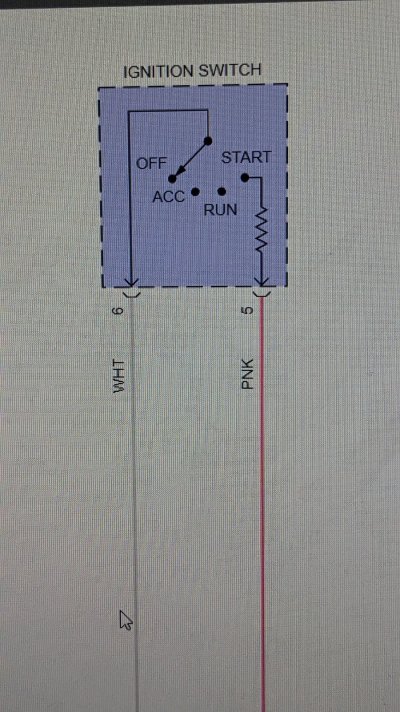
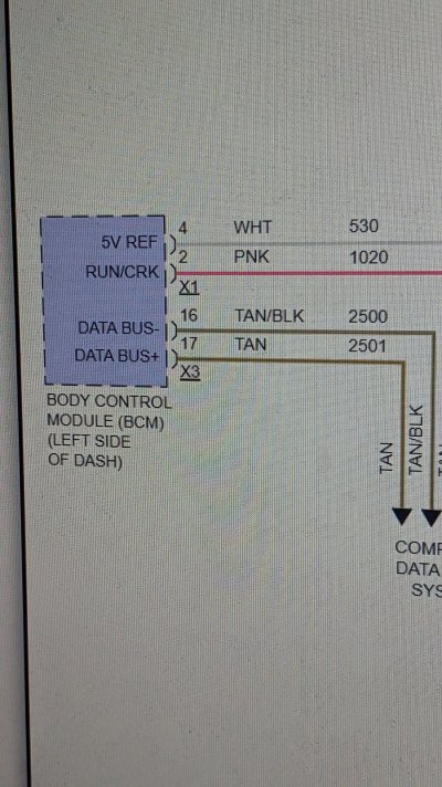
No it doesn't, no power to purple wire. So bad bcm or theft deterrent... Light won't go off.Does the starter solenoid click when you turn the key?
Yes it does, says crank signal yes as I turn the key. Crazy everything seems like it should turn over but doesn't. Can bus lines are all good 60 ohms battery disconnected. It's gotta be computer problems.will that scan tool show ign switch start request? like some will show if you've hit the search on say power windows, that way you know the search is working. is there a place somewhere that shows the ign switch is even sending the request to the bcm?
Yes it does, says crank signal yes as I turn the key. Crazy everything seems like it should turn over but doesn't. Can bus lines are all good 60 ohms battery disconnected. It's gotta be computer problems.
It's good. Starter works jumping relay. I think your right. Something isnt fully programmed. I don't have the equipment to program. Maybe I can just bring the ECM and bcm to them to test. I'm not sure.if that's the case, I have a bad feeling the shop didn't reprogram the replacement parts correctly. but that's a bit of a hassle and money to test.
I see there's a start fuse. 40amp #62. any chance it's blown?
Circuit/System Description
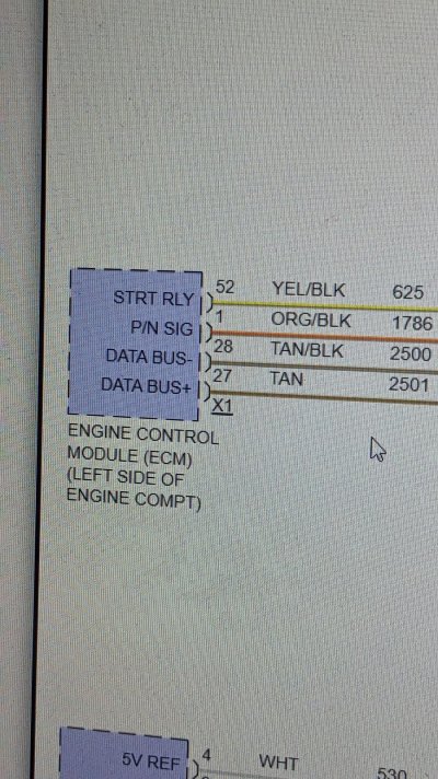
The engine control module (ECM) controls engine cranking based on a power mode input and the status of the park/neutral position (PNP) switch. With the transmission in Park/Neutral, voltage at the ECM PNP switch signal circuit is low. This indicates to the ECM that conditions are acceptable for cranking. When a power mode crank request is seen, the ECM applies voltage to the STRTR relay coil control circuit. This energizes the coil side of the relay, which pulls the switch side of the relay closed, applying voltage to the starter terminal S X2 and engaging the starter solenoid.
Diagnostic Aids
A misadjusted PNP switch (M30, M70) or shift control/range selector lever cable may result in a starter solenoid does not click condition.
Circuit/System Verification
Ignition ON, observe the scan tool ECM PNP Switch parameter while shifting the transmission through each range. The reading should change between Park/Neutral and In Gear.
If not the specified value, refer to PNP Switch Malfunction below.
Command the Starter Relay ON with the scan tool, or turn the ignition switch to the START position. The starter solenoid should click and the engine should crank.
If the solenoid does not click, refer to STRTR Relay Malfunction below.
If the solenoid clicks but the engine does not crank, refer to Starter Solenoid Clicks, Engine Does Not Crank.
Circuit/System Testing
PNP Switch Malfunction (MYC 6L80E, MYD 6L90E)
Inspect the range selector lever cable for proper adjustment. Refer to Range Selector Lever Cable Adjustment .
Ignition OFF. Disconnect the 16-way harness connector from the transmission.
Ignition ON. Measure voltage on the park/neutral signal circuit terminal 3 with a DMM. Verify that there is greater than 10 V on the park/neutral signal circuit.
If there is less than 10 V on the park/neutral signal circuit, test the circuit for an open or a short to ground. If OK, replace the ECM.
Ignition OFF, reconnect the 16-way harness connector to the transmission.
Remove the automatic transmission fluid pan. Refer to Automatic Transmission Fluid, Fluid Pan and/or Filter Replacement .
Disconnect the manual shift shaft position switch connector at the control solenoid valve assembly. Refer to Manual Shift Shaft Position Switch Replacement .
Ignition ON, verify that the scan tool PNP Switch parameter displays In Gear.
If not the specified value, replace the ECM.
Connect a 3 A fused jumper wire between the park/neutral signal terminal F at the control solenoid valve assembly and ground. The scan tool PNP Switch parameter should display Park/Neutral when the terminal is connected to ground.
If not the specified value, replace the ECM.
If all components test normal, test or replace the manual shift shaft position switch.
STRTR Relay Malfunction
Ignition OFF, disconnect the STRTR relay.
Ignition ON, transmission in Park/Neutral. Verify that a test lamp illuminates between the relay coil ground circuit terminal and B+.
If the test lamp does not illuminate, test the ground circuit for an open/high resistance.
Probe the STRTR Relay switch B+ circuit terminal with a test lamp that is connected to ground. Verify that the test lamp illuminates.
If the test lamp does not illuminate, test the B+ circuit for a short to ground or an open/high resistance. If the circuit tests normal and the STRTR fuse is open, test the relay controlled output circuit for a short to ground.
Connect a test lamp between the relay coil ground circuit terminal and the relay coil control circuit terminal.
Ignition ON, transmission in Park/Neutral. Command the Starter Relay ON and OFF with a scan tool, or turn the ignition switch between the START and RUN positions. The test lamp should turn ON and OFF when changing between the commanded states.
NOTE: The engine may begin to crank.
If the test lamp is always ON, test the relay coil control circuit for a short to voltage. If the circuit tests normal, replace the ECM.
If the test lamp is always OFF, test the relay coil control circuit for a short to ground or and open/high resistance. If the circuit tests normal, replace the ECM.
Connect the START relay.
Install a test lamp between the starter terminal S X2 and ground.
Ignition ON, transmission in Park/Neutral, command the Starter Relay ON with a scan tool, or turn the ignition switch to the START position. The test lamp should illuminate.
NOTE: The engine may begin to crank.
If the test lamp does not illuminate, test the relay controlled output circuit for an open/high resistance. If the circuit tests normal, test or replace the STRTR relay.
If all circuits test normal, test or replace the starter.
Component Testing
Relay Test
Ignition OFF, disconnect the STRTR relay.
Test for 60-180 Ω between terminals 85 and 86.
If not within the specified range, replace the relay.
Test for infinite resistance between the following terminals:
30 and 86
30 and 87
30 and 85
85 and 87
If not the specified value, replace the relay.
Install a 20 A fused jumper wire between relay terminal 85 and 12 V. Install a jumper wire between relay terminal 86 and ground. Test for less than 2 Ω between terminals 30 and 87.
If greater than specified range, replace the relay.
Repair Instructions
Perform the Diagnostic Repair Verification after completing the diagnostic procedure.
Control Valve Body Assembly Removal for shift shaft position switch replacement (MYC 6L80E, MYD 6L90E)
Control Valve Body Assembly Disassemble for shift shaft position switch replacement (MYC 6L80E, MYD 6L90E)
Control Module References for ECM replacement, setup and programming.
Excellent thank you very much for your help. I think I need a shop. Checking voltage today I discovered I have no power to the yellow power relay wire. The head scratcher is no fuse is blown. I tested right at the bottom of the fuse block nothing zero voltsso there's what my software says.. it's all pretty basic but just incase there's something in there to help that might have gotten missed. it does seem like that transmission sector is very important.