Dual Alternator wiring 07 Tahoe

Disclaimer: Links on this page pointing to Amazon, eBay and other sites may include affiliate code. If you click them and make a purchase, we may earn a small commission.

MalcDogg

Member
Joined
Mar 8, 2021
Posts
47
Reaction score
23
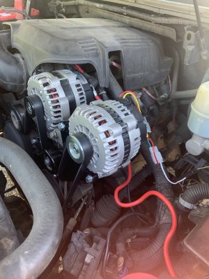
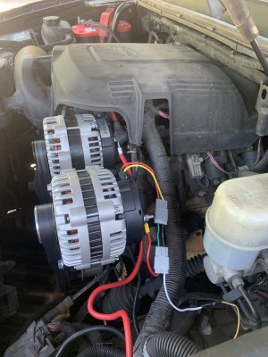
So I purchased the dual alternator bracket and second alternator 4 pin got everything installed but the second alternator is on putting out 11-12 volts and it’s not keeping my second battery charged

Can someone help me out?
 

exp500

Full Access Member
Joined
May 14, 2017
Posts
2,026
Reaction score
1,985
More info needed> Like Exactly how it is wired. How is the computer controlling 2nd alt? There are several threads here with multiple hi amp alts for reference.
 
OP
OP
MalcDogg

MalcDogg

Member
Joined
Mar 8, 2021
Posts
47
Reaction score
23
More info needed> Like Exactly how it is wired. How is the computer controlling 2nd alt? There are several threads here with multiple hi amp alts for reference.


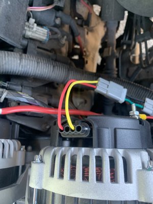
2nd alternator has a 4 pin
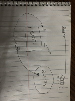
Only 2 wires from the 4 pin one wire with resistor is connected to ignition on
The other wire is connected to battery post on alternator and battery is connected there as while

8AFB1852-152A-49F9-86D2-ACE27BBE1007.jpeg
 

exp500

Full Access Member
Joined
May 14, 2017
Posts
2,026
Reaction score
1,985
Computer controlled OEM Alt in 1st position, 2nd position you have alt idling with no control. You didn't provide what you did for install of 2nd battery, No specs on Truck or alts. Standalone? Parallel? Called charging system for a reason.
I think you bought the wrong alt for your "upgrade", so it has the wrong voltage regulator for way you have it wired.
 
OP
OP
MalcDogg

MalcDogg

Member
Joined
Mar 8, 2021
Posts
47
Reaction score
23
Computer controlled OEM Alt in 1st position, 2nd position you have alt idling with no control. You didn't provide what you did for install of 2nd battery, No specs on Truck or alts. Standalone? Parallel? Called charging system for a reason.
I think you bought the wrong alt for your "upgrade", so it has the wrong voltage regulator for way you have it wired.


The 2nd alternator (253amp) came with the bracket and 4 pin connector but no instructions on how to wire it the connector only has 2 wires one as a resistor on it I’m pretty sure that wire goes to ignition power when key is on

I have a 2nd battery that stands alone for the second alternator

it’s a stand alone setup
 

exp500

Full Access Member
Joined
May 14, 2017
Posts
2,026
Reaction score
1,985
Post full specs for truck including part numbers for truck alt and#2 alt. 4 pin flat? 4 pin oval? Which 2 pins? or I'm done.
 

exp500

Full Access Member
Joined
May 14, 2017
Posts
2,026
Reaction score
1,985
So your yellow wire has the resistor? Post a link of what you bought. A 1 wire would have been simple. And It looks like you are reading alt voltage not batt voltage.
 
OP
OP
MalcDogg

MalcDogg

Member
Joined
Mar 8, 2021
Posts
47
Reaction score
23
So your yellow wire has the resistor? Post a link of what you bought. A 1 wire would have been simple. And It looks like you are reading alt voltage not batt voltage.


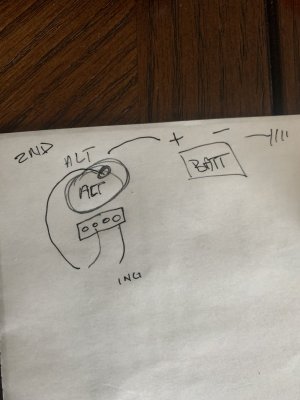
Myles I draw the diagram wrong the first time

image.jpg
 
OP
OP
MalcDogg

MalcDogg

Member
Joined
Mar 8, 2021
Posts
47
Reaction score
23
When I put my voltmeter on the alternator without the battery connected it’s only reading 12 volts or sometime lower not keeping the battery charged
I’m thinking maybe going with a deep cycle instead ‍♂️
 

exp500

Full Access Member
Joined
May 14, 2017
Posts
2,026
Reaction score
1,985
4 pin oval- PLFIS rear view pins- PL stator/light ,I F field/ign, S sense,, tab on top
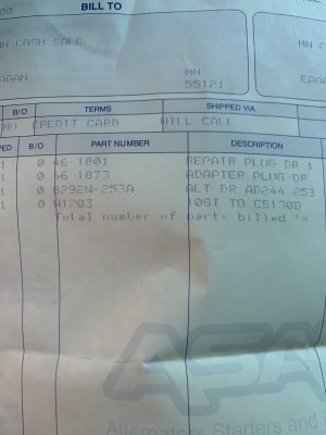
So yes wired incorrectly. And you have a diode inline, not a resistor in 46-1873 Is it installed Backwards? So were your plans to run alt at full output all the time? Your yellow wire should have Fuse inline. Wrong Harness/connector. But can be made to work. Use 1 wire on "I" For IGN only. P, S ,L unused. Try putting fusible link or fuse in Output somewhere before Battery.
 
Last edited:
OP
OP
MalcDogg

MalcDogg

Member
Joined
Mar 8, 2021
Posts
47
Reaction score
23
4 pin oval- PLFIS rear view pins- PL stator/light ,I F field/ign, S sense,, tab on top
So yes wired incorrectly. And you have a diode inline, not a resistor in 46-1873 Is it installed Backwards? So were your plans to run alt at full output all the time? Your yellow wire should have Fuse inline. Wrong Harness/connector. But can be made to work. Use 1 wire on "I" For IGN only. P, S ,L unused. Try putting fusible link or fuse in Output somewhere before Battery.


Ok so u telling me I have to move the L pin to F?

here’s the diagram

image.jpg
 

exp500

Full Access Member
Joined
May 14, 2017
Posts
2,026
Reaction score
1,985
Only use yellow wire. Sorry for confusion. I was not able to copy print pics.
Not having Your manufacturer of V/R Made it tough. If it is WAI you should be good.
Is Your last pic Post 15 from alt pin positions?(SFLP)Looking at face of connector Front View?
 
OP
OP
MalcDogg

MalcDogg

Member
Joined
Mar 8, 2021
Posts
47
Reaction score
23
Only use yellow wire. Sorry for confusion. I was not able to copy print pics.
Not having Your manufacturer of V/R Made it tough. If it is WAI you should be good.
Is Your last pic Post 15 from alt pin positions?(SFLP)Looking at face of connector Front View?


I haven’t tried it yet I’m gonna try that when I get home
 
OP
OP
MalcDogg

MalcDogg

Member
Joined
Mar 8, 2021
Posts
47
Reaction score
23
Only use yellow wire. Sorry for confusion. I was not able to copy print pics.
Not having Your manufacturer of V/R Made it tough. If it is WAI you should be good.
Is Your last pic Post 15 from alt pin positions?(SFLP)Looking at face of connector Front View?


Ok so I wired with just 1 wire and added the fuse before I connected the battery the alt post was reading 12.1v connected the battery and drove around now it’s only reading 11.3v and going down

I want it to hold the battery at at least 13.5 for my sound system

what do I need to do to get this to work
 

exp500

Full Access Member
Joined
May 14, 2017
Posts
2,026
Reaction score
1,985
Have you verified the diode facing correct direction or removed? Voltage at alt Ign plug term when key on. Plugged in and unplugged.
You giving up nearly no info isn't helping- so where oh where is your secret vendor that can't help You?
 
OP
OP
MalcDogg

MalcDogg

Member
Joined
Mar 8, 2021
Posts
47
Reaction score
23
Have you verified the diode facing correct direction or removed? Voltage at alt Ign plug term when key on. Plugged in and unplugged.
You giving up nearly no info isn't helping- so where oh where is your secret vendor that can't help You?


Ok let’s start at the beginning
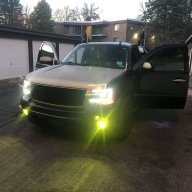
2008 Chevy Tahoe LS
I have a red top battery that I wanna use for my sound system to power my amps I brought the dual alternator bracket to run 2 alternators
2nd alternator will be stand alone to power the second battery

the 2nd alternator I brought from a vendor who supplied me with the doide and 4 pin connector he told me to wire the doide to ign wire and second wire to alternator post with the battery I did that and it’s wasn’t keeping the battery charged I want the second alternator to at least maintain the battery at 13.5 or more volts to handle the power of the amps

the vendors is no help at all
I’m thinking maybe the 2nd alternator could be bad?

Ur more helpful then they ever been if there is any info u need to help me get this done let me know please
 

Forum statistics

Threads
138,090
Posts
1,998,709
Members
103,016
Latest member
BadDaddy2003

Latest posts

Back
Top