
Autoride bypass sensors

Disclaimer: Links on this page pointing to Amazon, eBay and other sites may include affiliate code. If you click them and make a purchase, we may earn a small commission.

Bigjimmy

Member
Joined
Jun 9, 2016
Posts
63
Reaction score
22
I've replaced Autoride with Bilsteins front(adjustable)and rear(also Moog springs in rear and a front level spacer.It rides great again even with 270/60/20 Nitto All Terrains
The rear plugs for sesnsors only have 2 wires so that was straightforward to cut and fit bypass modules but front plugs have 3 wires and I'm a bit hesitant to cut anything before I get a bit of advice
Vehicle is 2008 Yukon Denali XL
Any help much appreciated

 
OP
OP
Bigjimmy

Bigjimmy

Member
Joined
Jun 9, 2016
Posts
63
Reaction score
22
Thanks he's the guy whose given me lots of good advice and parts numbers etc in the past I was trying not to bother him again though....
 
OP
OP
Bigjimmy

Bigjimmy

Member
Joined
Jun 9, 2016
Posts
63
Reaction score
22
Not heard back from @01Konvict which isn't like him,maybe on vacation or something.
Does anyone else care to pitch in with the info?
 

01Konvict

Boats n Hoes
Joined
Jan 16, 2011
Posts
2,747
Reaction score
707
Location
Raleigh/SML
Not heard back from @01Konvict which isn't like him,maybe on vacation or something.
Does anyone else care to pitch in with the info?

Sorry boss been away for a few days haha. As far as the new models for resistor bypass on the front shocks it should be only two wires. Here's a video that shows how to do it. Use heat shrink instead of tape though and I would prefer a crimp on splice joint instead of wire twisted together. Only unknown is what resistor you need to remove the compressor. I would remove the fuse in the under hood box to start.
 
OP
OP
Bigjimmy

Bigjimmy

Member
Joined
Jun 9, 2016
Posts
63
Reaction score
22
image1.jpeg
image2.jpeg
 

01Konvict

Boats n Hoes
Joined
Jan 16, 2011
Posts
2,747
Reaction score
707
Location
Raleigh/SML
Definitely 3 wires!

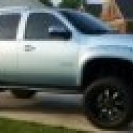
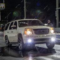
From the video and compared to your picture I would suggest the yellow and green wire. Not sure what the third wire does unless its a trace wire. I would test the resistor by placing a soldered wire into the female plug ends testing each of the two wire circuit combinations until it clears. Then use a quick splice connector on the wire side for long term install like th pics below. It wont hurt the computer because its a resistor and doesn't input any power. Definitely different for those euro models. How about a few pics of the whole truck?
42403228.jpg

8dcf97ec-c7f1-464b-b53c-730a2133c2bf.jpg
 
OP
OP
Bigjimmy

Bigjimmy

Member
Joined
Jun 9, 2016
Posts
63
Reaction score
22
Thanks for advice,I'll pass it on to guy who usually works on it. I'll get a few pis up when it's nice and clean,roads are salted here this time of year, what a mess it makes
 

01Konvict

Boats n Hoes
Joined
Jan 16, 2011
Posts
2,747
Reaction score
707
Location
Raleigh/SML
I was wondering if it was the sensor and not the shock tower plug, that might explain the three wires?
 
OP
OP
Bigjimmy

Bigjimmy

Member
Joined
Jun 9, 2016
Posts
63
Reaction score
22
My mistake it's shock tower plug....3 wires and only 2 on bypass modules?
What goes where?
 

01Konvict

Boats n Hoes
Joined
Jan 16, 2011
Posts
2,747
Reaction score
707
Location
Raleigh/SML
My mistake it's shock tower plug....3 wires and only 2 on bypass modules?
What goes where?

So the 3 wire plug was for the ride height sensor and you found the 2 wire plug for the shock? If so then connect the 3 wire back to ride height sensor and I saw you have already fixed them so they don't move. Connect the resistor to each of the 2 wire shock plug.
 

Forum statistics

Threads
138,106
Posts
1,999,223
Members
103,032
Latest member
albac
Back
Top