6.2L L94 & 6L80 into my 1992 Blazer

Disclaimer: Links on this page pointing to Amazon, eBay and other sites may include affiliate code. If you click them and make a purchase, we may earn a small commission.

OP
OP
N

Nak

Full Access Member
Joined
Aug 15, 2013
Posts
185
Reaction score
10
They give you a routing diagram for use if all accessory brackets are Holley. They don't if you're using the Holley AC bracket and GM for all the rest. Not a big deal because the routing is pretty much the same as stock; you just add the AC pulley. BTW, the Holley routing would not work at all with the GM brackets, the driver's side idler is in an entirely different location.

Absolutely, I'm going to call Holley. I'm not expecting a lot of help though; last time I called them it wasn't very helpful... I'll see what they say though. It's easy to see why they have the idler circled in red; it's very much needed with the full Holley accessory brackets.

The other nice thing about eliminating that pulley is that the belt would be a commonly stocked belt. With the pulley in place the belt is a special order item. I couldn't find a single parts store that carried it in stock. Nice to be able to replace it easily if it fails in the boonies somewhere. Not a deal breaker, but still...

---------- Post added at 09:36 AM ---------- Previous post was at 09:15 AM ----------

Awesome project man!

Thanks! Nice looking truck BTW. How do you put the bigger pic in your signature? I can only put that small pic in mine???
 
OP
OP
N

Nak

Full Access Member
Joined
Aug 15, 2013
Posts
185
Reaction score
10
Just spent all day working on cleaning up the wiring from the old harness. The wires going to the old PCM will be cut off and labeled leaving a long pigtail for possible future use for whatever wires need to go from engine bay to cabin. Some wires need to stay--AC and the like. Thank god for wiring diagrams; there's been a couple of wires I might have cut that I actually need... There's been a couple of anomalies as well. A couple of different circuits listed as going to the same pin on the PCM. An error I'm sure. Also, the power--pink wire--to the coil shows NO FUSE? That seems unlikely, but the diagram shows the circuit coming from the ignition switch with no fuse protecting it--just the fusible link that protects the ignition switch itself. This might be true, but I'm going to power the switch and start pulling fuses to see if there is in fact a fuse protecting that circuit. I need to know, because I plan on powering the new harness with that circuit.
 
OP
OP
N

Nak

Full Access Member
Joined
Aug 15, 2013
Posts
185
Reaction score
10
OK, due to having to work and Easter, I haven't got a lot done other than chase parts and finish the belt. I haven't cut the upper pulley off--yet. I talked to Holley, they wouldn't express an opinion either way. I'm leaving it for now...

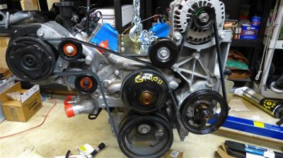
All of the following ONLY refers to using the Holley AC bracket with GM brackets like mine. If you are using all Holley brackets you should probably just follow their directions. Also, I am using the later R4 compressor with the 4.5" pulley. If you have a 5" Pulley, as Holley recommends, then your measurements will be different. (Measured at the pulley surface.)

This is what I did: Holley's directions are not very explicit if you're using the GM brackets for the Alternator and the PS pump. If you look at the picture in this post, there are two pulleys by the AC compressor--upper and lower. The upper is the one I don't think you really need, looking at the picture you should be able to see why. When you buy the kit, it does not come with the tensioner--the bottom pulley--they specify what one to buy. They also specify a pulley you need to buy to replace the one that comes with the tensioner. You then take the one that was on the tensioner and use it as the upper pulley. They also list a second pulley you can use as the upper pulley; it is a smaller pulley that allows more clearance and is in fact required in certain setups. (The bigger one that came with the tensioner can interfere with some throttle bodies.)

The new lower pulley they specify is 76mm in diameter. That probably works great with all Holley brackets, but there are other choices. I ended up replacing it with a 70mm pulley. That allows me to not cut off the upper pulley boss and still use a common belt. It also puts the belt right in the middle of the acceptable range.

When you put the belt on, you check it with marks on the tensioner. Holley describes two marks in the directions--confusing because there are actually three marks. When you look at the tensioner, there is a reference mark. It lines up somewhere along the three reference marks. Here is what is not included in the Holley directions: The two marks closest together show the range for a brand new belt. As the belt ages and stretches, you use the two marks furthest apart to determine if the belt is still serviceable. If you use the pulleys specified by Holley, you can't find a belt that ends up in the "New" range. At least you can't with my setup. The Dayco 5061093 is too short and the Dayco 5061098 is too long. There is nothing in between. (Cross reference those numbers to see other brands; there is still nothing in between in any brand.) Even with the smaller Upper pulley you are out of luck. You could cut off the Upper Pulley Boss. Doing that results in the 5061093 fitting--barely. (BTW, the 5061093 is commonly available, the 5061098 is special order only everywhere that I tried.) However, if you switch to the smaller upper pulley that Holley specifies, AND you switch to a 70mm lower pulley, the 5061093 fits right in the middle of the acceptable range. I haven't run the engine yet, so this presupposes that I am getting the tension where it will be after the engine has run. I believe I have, but I'll have to verify after the L94 is running.

Anyways, I'm leaving the upper pulley boss intact because it seems like I get the best results this way. I may change my mind after I run the engine the first time.

I used Dayco parts because their website allows you to look up belt and pulley specifications.

http://www.daycoproducts.com/online-...1?part_type=20
http://www.daycoproducts.com/online-...1?part_type=60

You need a single bearing 17mm ID pulley for both upper and lower pulleys. (A dual bearing pulley may or may not work; I have no idea.) The upper pulley is 6 rib, the lower pulley is smooth. Changing the diameter of the lower pulley makes a much bigger difference in belt length than changing the diameter of the upper pulley.

BTW, The Holley directions for determining belt length didn't work so well. They tell you to subtract 1 1/8 inches from your measurement. I got much closer by not making the subtraction. Why? using a string to measure belt length measures inside circumference. Belts are spec'd using outside circumference. Regardless, I only got close, be prepared to return the belt and try another one.

The easiest way to install the belt is to remove the upper pulley and then install the belt. Then install the upper pulley.

BTW, you can't play with the idler pulley by the alternator. no room to go bigger and going smaller would cause belt interference with an alternator mounting bolt.

 

Attachments

  • Belt Routing (Custom).JPG
    Belt Routing (Custom).JPG
    67.7 KB · Views: 55
Last edited:
OP
OP
N

Nak

Full Access Member
Joined
Aug 15, 2013
Posts
185
Reaction score
10
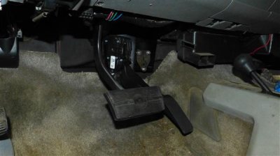
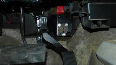
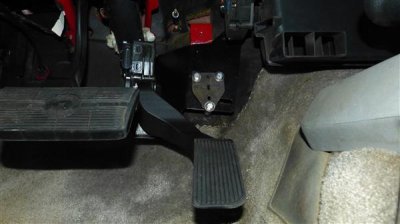
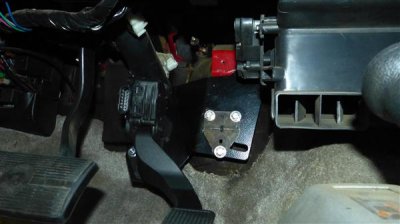
Accelerator pedal is in. I got a bracket from Motech (LSWrangler.com) along with my harness. The bracket is designed to mount a DBW truck pedal in a jeep, but it worked great for my rig as well. I had to drill thee holes--obviously the jeep mounting holes didn't line up--but the angle of the bracket put the pedal in what I feel is an ideal position. I used the original pedal hold down plate as a guide to drill the holes, and then used it as a big washer to stabilize the bracket. I used 1" nylon spacers to space the Motech bracket out. A single washer between the bracket and the lower spacer was required to tweak the throttle position. Three M6 x 1.0 x 60mm bolts were required.
 

Attachments

  • P1030622 (Custom).JPG
    P1030622 (Custom).JPG
    41.4 KB · Views: 61
  • P1030623 (Custom).JPG
    P1030623 (Custom).JPG
    42.2 KB · Views: 54
  • P1030624 (Custom).JPG
    P1030624 (Custom).JPG
    42.8 KB · Views: 59
  • P1030625 (Custom).JPG
    P1030625 (Custom).JPG
    44.2 KB · Views: 60

THE YETI

Director of Operations
Supporting Member
Joined
Apr 29, 2009
Posts
27,159
Reaction score
15,451
Location
South FL
how the heck did I miss this one! Pretty slick project you got going on there!
 
OP
OP
N

Nak

Full Access Member
Joined
Aug 15, 2013
Posts
185
Reaction score
10
Thanks! My goal is to have it back on the road by June 1...

---------- Post added at 10:28 AM ---------- Previous post was at 10:18 AM ----------

Back to pulleys... BTW, I forgot to mention the black bolt that comes with the new tensioner. Make sure you use anti-seize on it every time you install it! The very first time I torqued it down it galled the aluminum! The silver color bolts on the engine and supplied by Holley did not show this behavior. I still used anti-seize for final installation.
 

97Tahoe2d4x

Member
Joined
Apr 1, 2013
Posts
63
Reaction score
3
Location
SF Bay Area
Looks like a very well thought-out project you have going here.
I'm following this thread with much interest, particularly with 6L80 swap.

Keep up the good work and keep those pics coming.
 
OP
OP
N

Nak

Full Access Member
Joined
Aug 15, 2013
Posts
185
Reaction score
10
Thanks! Positive feedback really does help...

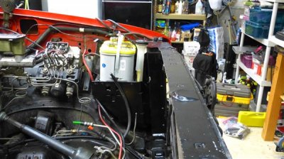
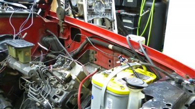
Got the battery and windshield washer reservoir relocated. I had to wait on new parts, the driver's side battery mount for a 1992 does not leave room for the washer res under it. So I had to order the support for a 96 - 99 from GM. The battery tray itself is no longer available, but I was able to find a NOS one on ebay. The ECM will go where the reservoir was, above the ABS module. I have to find some soft rubber washers/spacers to isolate the ECM from vibration. Any ideas?

For the new battery tray and support, one hole on the radiator support was in the correct location already, all other mounting holes had to be located and drilled. Except for the bolt that supports the top of the fill tube. There was a ground bolt right where it needed to be. I'll relocate the ground.

I also finished organizing and trimming the old harness. I'm waiting on corrugated nylon tubing to finish up the harness. Amazing how hard it was to find. I ordered some from a ******* on Amazon, but when it showed up it was polyethylene. I order the good stuff from a place in MN; hopefully when it gets here Wednesday it really will be nylon.

Still to go this week: Finish the wiring. Relocate the trans crossmember. Get the steering column side of the cable shift linkage installed. Install the new fuel tank & run the fuel lines. Clean the fresh air vent intake & fix whatever the hell leaks there. Right now the plan is to drop in the engine, trans and transfer case on Sunday... If I don't get called in to work.

Also, since I'm going with dual exhaust, I need to figure out heat shielding for the driver's side of the trans--I have a factory shield for the passenger side--and the fuel & brake lines. Any ideas on this would be welcome too!!

Also, I'm debating one thing: Cold air intake, which would go where the old battery was; OR maybe skip the CAI and go with a second battery? The original CAI is WAY too restrictive. Or maybe have a CAI scoop mounted on the fender feeding the original location and have an aux battery too. it just seems like it would be hard to make a fender mounted scoop look nice... Sheet metal work is NOT my forte.
 

Attachments

  • P1030626 (Custom).JPG
    P1030626 (Custom).JPG
    68.5 KB · Views: 55
  • P1030627 (Custom).JPG
    P1030627 (Custom).JPG
    68.8 KB · Views: 56
  • P1030628 (Custom).JPG
    P1030628 (Custom).JPG
    66.3 KB · Views: 64
  • P1030629 (Custom).JPG
    P1030629 (Custom).JPG
    69.1 KB · Views: 56
Last edited:
OP
OP
N

Nak

Full Access Member
Joined
Aug 15, 2013
Posts
185
Reaction score
10
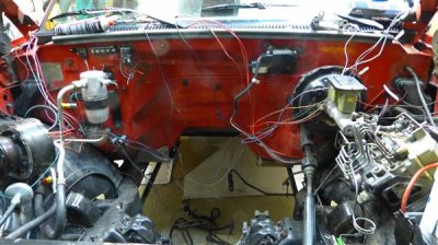
BTW, The original Coil power has been relocated up to the ECM area, it will power the new harness. One of the old injector circuits will power the new front axle actuator. The '92's had a really crappy actuator that locked in the front axle. It relied on heating a wax pellet to actuate. Seriously? Anyways, I've installed a later one which uses a solenoid type activation. REALLY worthwhile upgrade by the way. It used to take ages to lock in in cold weather. Now it's damn near instant. I've powered it in the past with a direct battery connection; the injector circuit is fused and hot in start & run. Much better.
 

Gzes

the drifting 2dr
Joined
Aug 9, 2011
Posts
5,433
Reaction score
53
Location
Wichita tx
Nice project. Now I kind of want to hurry up and get the stepside c10 I've been trying to get and swap it
 
OP
OP
N

Nak

Full Access Member
Joined
Aug 15, 2013
Posts
185
Reaction score
10
Thanks! An LS Stepside would be a nice rig!

So much for cable shifting! I was planning to switch to cable shifting with a kit from "IdidIt", but there is no way to hook up the linkage to the steering column. There just isn't enough room between the steering column, the frame rail, the vacuum assist brake can and the exhaust. It works on the 6L80 side, so maybe in a different vehicle. After a few hours playing with that, I gave up. Went down to the local trans shop and took some careful measurements on a 4L60e. It turns out the shifting shaft on the 6L80 is 1 3/16" aft and 1/8" down compared to the same shaft on the 4L60. So I'm going to get 1 3/16" welded on to my original shift rod. After the trans is in, I'll see if the rod that goes across to the trans needs to be lengthened/shortened. Should have just done this to start with. The shifting shaft on the 6L80 is clocked identically to the 4L60, so this should work pretty well. At least I hope so!

Also, I was planning on running the charcoal canister from a 2012, another bad idea. Too, big, no place to put it. There would be room with single exhaust, but with duals--no way. After further investigation the stock canister from 98-99 mounts right to my new battery support and will work just fine using the 98-99 vent solenoid as well. I'll run 5/8" line from the tank rollover valves to the can. Should work identical to 2012 setup; actually maintenance on the system will be easier. I'll need a new gas cap as well.
 
OP
OP
N

Nak

Full Access Member
Joined
Aug 15, 2013
Posts
185
Reaction score
10
Woo Hoo! Engine, trans & Transfer case goes in in the morning! I've so busy between work & the swap I haven't had time to post. I'll post pics later, but what I've done: Run a 5/8" line from the rollover valve to the engine bay for evap. Run the fuel lines. Finished organizing the '92 harness. I'll put on the corrugated loom after the engine is in. Dealt with a total length issue. (More on that later...) Designed the new shift linkage. Spent hours on the Trans mount to trans bolts torque spec. The service manual is wrong I believe. It says 49 ft pounds. No way. M8 bolts into aluminum? I don't believe it. I'm going with 36 and loctite 242. Trimmed the boss that I pointed out earlier on the block. I tried on a motor mount, less than a sixteenth of an inch clearance. After trimming, about 1/4". drilled new holes for the trans X-member and the shift linkage. Lots of misc stuff. :)
 
Last edited:
OP
OP
N

Nak

Full Access Member
Joined
Aug 15, 2013
Posts
185
Reaction score
10
And in! Pics to come...

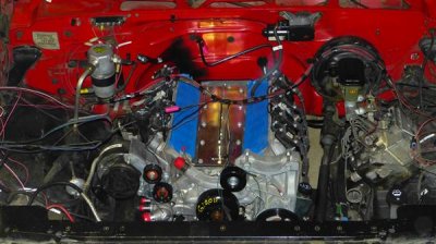
L94, 6L80, NP241 and the rear drive shaft are in.

The L94 fits like a glove. No news here, lots of people have done this swap. Although it surprises me I've never seen anything about that one boss I cut down. It was 1/16" or less from the motor mount. WAY too close for my taste. Any movement at all and you'd be tapping block to mount. Not good. I trimmed it down to where the reinforcement webbing started. Just about 1/4" clearance now. Very glad I did this.

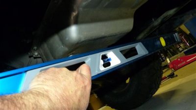
The 6L80 fit's like it was meant to be there. Pics to come, but here are some notes you'll find important if you ever want to drop a 6L80 in this year range OBS: I moved the Trans cross member aft one inch. That was perfect for the standard 1" setback motor mounts. (Keeping the rear of the engine in the original 1992 location.) It fits just right. The original shift linkage fits perfect with NO modifications. (Rod type linkage.) I drilled a hole 1 3/16" aft for the linkage--I shouldn't have. The original hole works better. The 6L80 gear shift shaft is clocked identically to the old 700R4. The distance from the frame to the trans works perfect for the original linkage too. Again, NO mods are required for the rod type shift linkage; it fits just fine as is. The stock truck pan sits 1 1/4" above the frame rails, so it fits just fine too. Plenty of room to go with the low profile PML pan if you want to go that route. No need to go with a really low profile pan like a G8 pan. The dipstick tube was somewhat easy to install after the engine, trans and Transfer case are in. No need to mount that before bolting the trans to the cross member. The cross member installs somewhat easy after all is in too. Just jack the trans up as high as it will go. This isn't high as the 6l80 does not have tons of room between the trans and the body. About 5/8" clearance or so at the top? Because of that, you have to work the trans mount into place on the cross member BEFORE bolting the cross member in place. Then slide the cross member in to position and lower the trans to the cross member, then install the trans mount to trans bolts. If you bolt the mount to the trans first, you don't have room to get the cross member in place.

Sequence: Engine in--1" setback, trans in and bolted/torqued to the engine, transfer case mounted to trans, raise trans as high as it will go, put cross member in place, install trans mount to cross member, loosely start mount to trans bolts, install cross member to frame bolts--1" aft of original location, torque trans to mount bolts. This ends up with the transfer case being in the same position as it was originally.

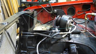
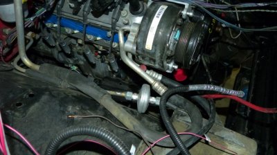
I went with the Holley R4 AC bracket, so I wouldn't have to disconnect the AC at all. That didn't work out so well. The bracket moves the R4 considerably more outboard than it was, enough so that I'll need new hoses. I got it mounted, but I had to bend the hell out of the hard line mounting to the back of the R4, and it still has the hose in a bad place. To do over again, I'd have had the system emptied, and gone with a Sanden AC compressor instead of the R4. Oh well... The R4 has always kept my rig plenty cool. Nothing bad to say about the Holley bracket, it just moves the R4 where it can fit. It looks very factory.

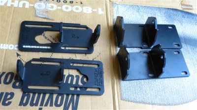
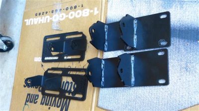
I ended up going with KDS instead of Dirty Dingo motor mounts. I like the KDS mounts a lot better because of the way they locate the mount properly. Just drop the engine down onto the locating pins, throw in the thru bolts and done. Just that easy. The negative about the KDS mounts is that I don't like the way they come. They are not welded completely around, I'll show pics of this later. I had mine welded up completely. This warped the mounts since no jig was available. No big deal, because 10 bucks took care of that at a custom metal bending shop. Then I had them powder coated. So, I'm into them about $170. I have no idea why they aren't completely welded from KDS. They are water jet cut and designed very nicely. Great mounts. But leaving crevices is just an invitation to corrosion and failure in my humble opinion. Nothing wrong with the DD mounts either, just harder to get the motor perfectly level. Very doable and lots of people have done it, I just like the KDS style more. Closer to the way the factory mounts are designed.

I did not leave any engine mount bolts loose as Dirty Dingo and KDS recommends. I measured very carefully, and got the mounts set in precisely the factory location. The front surface of the rear motor mount plate--the part that mates to the rear of the frame mounted mount--needs to be 14" on both sides. I used a straight edge across the back of the engine so I could measure straight back and not at an angle. I torqued the mounts down and used loctite 242. This worked out perfect. Just make sure you measure VERY precisely. Fore and aft an 1/8" won't make a big difference, but the left side MUST be exactly where the right side is. Otherwise the trans mount will be off left to right.
 
Last edited:
OP
OP
N

Nak

Full Access Member
Joined
Aug 15, 2013
Posts
185
Reaction score
10
Dirty Dingo and KDS motor mounts. The dirty dingo mounts have more range, the KDS are 1" setback +/- a little bit. The KDS have locating slots that mate with the factory motor mounts and make installation a snap. The Dingos are fine to use as is, I had the KDS welded completely up, straightened and then powder coated. (The welding warps them.) I don't like the way the KDS come partially welded. Nothing wrong with the Dingos, I prefer the KDS after they are finished up. The Dingos are probably easier to tighten up the bolts if you leave them loose for installation. I'd rather make damn sure they're in the right position before dropping the motor in.
 

Attachments

  • P1030634 (Custom).JPG
    P1030634 (Custom).JPG
    55.4 KB · Views: 48
  • P1030635 (Custom).JPG
    P1030635 (Custom).JPG
    58.5 KB · Views: 47
OP
OP
N

Nak

Full Access Member
Joined
Aug 15, 2013
Posts
185
Reaction score
10
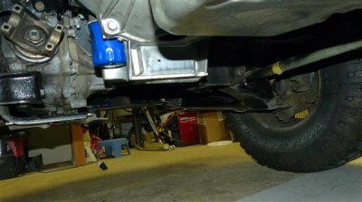
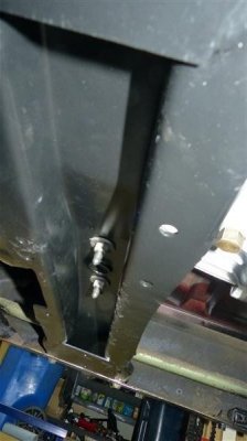
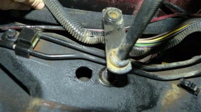
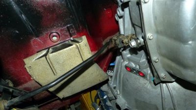
Some post install pics: (The middle one is the trans cross member, the last two show trans shift linkage.)
 

Attachments

  • P1030674 (Custom).JPG
    P1030674 (Custom).JPG
    39.3 KB · Views: 63
  • P1030676 (Custom).JPG
    P1030676 (Custom).JPG
    47.9 KB · Views: 61
  • P1030677 (Custom).JPG
    P1030677 (Custom).JPG
    32.4 KB · Views: 58
  • P1030678 (Custom).JPG
    P1030678 (Custom).JPG
    53.9 KB · Views: 64
  • P1030679 (Custom).JPG
    P1030679 (Custom).JPG
    51.4 KB · Views: 65
Last edited:
OP
OP
N

Nak

Full Access Member
Joined
Aug 15, 2013
Posts
185
Reaction score
10
One more...
 

Attachments

  • P1030686 (Custom).JPG
    P1030686 (Custom).JPG
    62 KB · Views: 62
OP
OP
N

Nak

Full Access Member
Joined
Aug 15, 2013
Posts
185
Reaction score
10
The AC post install:
 

Attachments

  • Hoses.jpg
    Hoses.jpg
    100.4 KB · Views: 52
OP
OP
N

Nak

Full Access Member
Joined
Aug 15, 2013
Posts
185
Reaction score
10
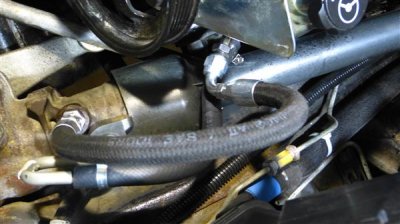
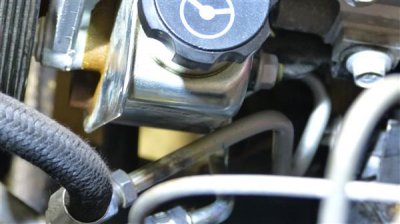
It seems like there's just a million little details... I've got the power steering done. The stock return line from a 2012 works perfect; I had to fab up the pressure line because of the electric fans. I cut the 2012 hard line from the pump where it comes even with the front of the pump. Then had a -6 AN male fitting welded on. I put a O-ring to -6 AN fitting in the steering box then ran a line between them. I'll add pics later.

I'm using the factory hard lines for the Trans cooler. I had to cut them half way up the engine block for clearance. Had -6 AN fittings welded to them there, I'll run hose the rest of the way.

The factory hard lines for the oil cooler don't fit at all, so I'm going with an improved racing low profile adapter/thermostat at the block, then hose from there. http://www.improvedracing.com/oil-c...ler-thermostat-for-ls-engines-180f-p-209.html

I found out that the Alternator I have won't run without massive work, so I'm swapping the 2 pin voltage regulator for a 4 pin voltage regulator off of an AD244 alternator. The alternator I have is a 160 amp model with 5 miles on it, so well worth keeping.

I have to trim the fan shroud some more; the evap can interferes with it a bit. Just a bit of trimming will fix it.

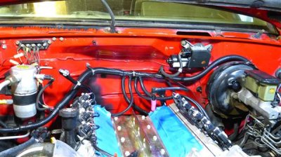
The original harness is all trimmed and covered with nylon corrugated loom. I re-routed it a bit to keep it further away from the exhaust. All splices were done with Ancor marine grade wire and Ancor marine grade butt splices with adhesive line heat shrink. That keeps all of the connections waterproof, plus the marine grade wire should outlast the truck. I have like 10,000,000 feet of loom leftover. I couldn't find nylon loom anywhere but at Waytek wire in 100' rolls. Couldn't find it locally and most of the online stuff is polyethylene. Several online places sold what they claimed was Nylon, turned out to be poly.

The intake goes on tomorrow, I'll get what I can get done this week and then it goes in for an exhaust system on Thursday. Mandrel bent stainless dual exhaust is my plan right now. I want both tubes to dump out the passenger side though. I've heard that dumping out both sides sounds terrible in V4 mode...
 
OP
OP
N

Nak

Full Access Member
Joined
Aug 15, 2013
Posts
185
Reaction score
10
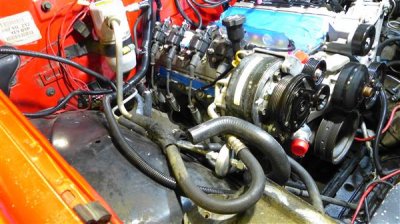
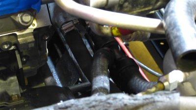
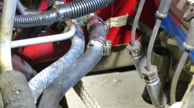
Got the heater hoses done. I used a stock 2012 return line and standard hose for the hot line. The stock return line has a 3/4" connection to the motor and a 5/8" connection to the heater core. Perfect. It also has a tee to the surge tank. (I'll be running the 2012 surge tank.) The hot line is 5/8" out of the motor and 3/4" into the core. I just used an adapter to mate the two.

I also got a bunch of minor details done, tons left to go! Still on track for the exhaust on Thursday.
 

Attachments

  • P1030688 (Custom).JPG
    P1030688 (Custom).JPG
    55.3 KB · Views: 59
  • P1030689 (Custom).JPG
    P1030689 (Custom).JPG
    48.5 KB · Views: 59
  • P1030690 (Custom).JPG
    P1030690 (Custom).JPG
    74.4 KB · Views: 54
  • P1030692 (Custom).JPG
    P1030692 (Custom).JPG
    45 KB · Views: 52
  • P1030693 (Custom).JPG
    P1030693 (Custom).JPG
    53.6 KB · Views: 54
OP
OP
N

Nak

Full Access Member
Joined
Aug 15, 2013
Posts
185
Reaction score
10
Wiring pic... Nothing running down by the exhaust now. The starter solenoid is re-routed around and in from the front.
 

Attachments

  • P1030694 (Custom).JPG
    P1030694 (Custom).JPG
    73.4 KB · Views: 48

Forum statistics

Threads
138,117
Posts
1,999,576
Members
103,040
Latest member
CrackerJack135

Latest posts

Back
Top