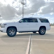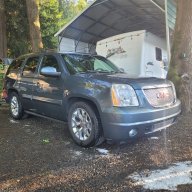
6.2L L94 & 6L80 into my 1992 Blazer

Disclaimer: Links on this page pointing to Amazon, eBay and other sites may include affiliate code. If you click them and make a purchase, we may earn a small commission.

Nak

Full Access Member
Joined
Aug 15, 2013
Posts
185
Reaction score
10
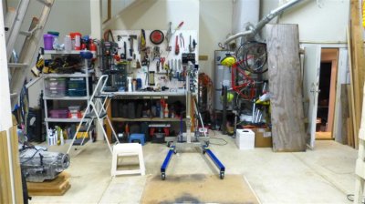
I have to finish my basement remodel first, should be done in a week or two. Then I can put away all of my wood working tools and get ready for the engine swap.

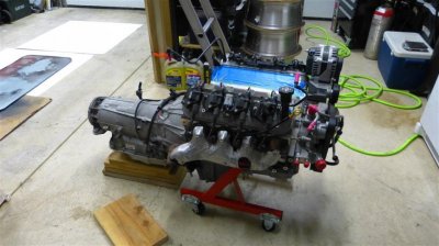
I've studied this swap for about a year now and recently acquired a 2012 L94 6.2L with 5 miles on it. The 6L80 is out of an identically optioned 2012 Denali; it has 10K for mileage. I'm hoping the swap itself won't take more than a month or two. (This won't be my first engine swap, but it will be my first LS swap.) My plan is to keep the motor and trans as close to stock as possible. My intent is to keep the BCM in the mix for cruise and "tow" mode.

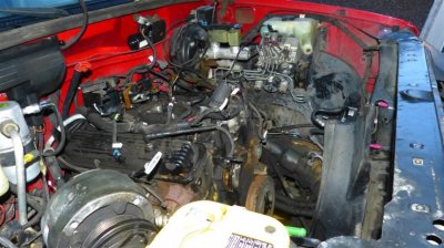
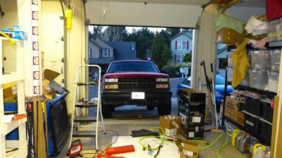
I've owned the '92 since it was 6 months old. It's in pretty darned good shape, but the tranny is getting tired. I've already swapped in a freshly built 14 bolt SF rear end with an Eaton Trutrac. 3.73 gears. Once the engine swap is done, I'll redo the interior and then I'll re-paint to finish it off.


I'm sticking with the original NP241 Transfer case. Looks like I should just need a new input gear to match the 6L80. Measuring the 6L80 it's just about identical in length to my 700R4, so I should be good with the stock drive shafts and TC shift linkage.

I've collected most of my parts:
-Wire harness from Motech complete with BCM for stock cruise control, tap shifting and Tow mode.
-New Gas tank from a 1998 Yukon. That allows me to use a '98 fuel sender/pump. The '98 uses the correct resistance range for the fuel sender. It also has a fitting for a fuel tank vapor pressure sender.
-'98 fuel sender/pump assembly
-2001 Corvette Fuel Filter/pressure regulator
-2012 truck air cleaner/MAF/intake plumbing and electric fans
-motor mounts
-Holley AC brackets

Still need:
-IdidIt conversion to cable shifting.
-Fuel lines and fittings
-oil cooler & trans cooler & lines and fittings.
-EVAP setup.
-PCV catch Can
-input gear for the NP241

-Exhaust: Still undecided. I'm getting a bid for a complete exhaust from "Get Bent" here in Portland, Oregon. Steve, the owner, has given me a ball park figure of $1800 for a mandrel bent stainless steel exhaust complete from the exhaust manifolds back. (Including two cats.) I'll have a firm price after he gets the truck on a lift and we agree on exactly what the exhaust will look like. I would love to hear any advice on exhaust you guys have!

Big question mark here: How low will the stock oil pan sit? It looks to me like it will be the lowest thing by an inch or so. Anyone who's done this, PLEASE help me out here! I'm thinking I need a new pan, but all of the options I've seen are not compatible with DOD. (Yes I am running the DOD and VVT...) Where does the stock truck pan sit on these trucks? Any pictures? This truck will be driven off road occasionally, so ground clearance is an issue.

Thanks for any help in advance! I'll start getting up pictures in the next couple of weeks.
 
OP
OP
N

Nak

Full Access Member
Joined
Aug 15, 2013
Posts
185
Reaction score
10
Started today!
 

Attachments

  • P1030573 (Custom).jpg
    P1030573 (Custom).jpg
    100.5 KB · Views: 138
  • P1030576 (Custom).jpg
    P1030576 (Custom).jpg
    98.7 KB · Views: 143
  • P1030578 (Custom).jpg
    P1030578 (Custom).jpg
    104 KB · Views: 133
  • P1030579 (Custom).jpg
    P1030579 (Custom).jpg
    103 KB · Views: 131
  • P1030581 (Custom).jpg
    P1030581 (Custom).jpg
    101.5 KB · Views: 134
OP
OP
N

Nak

Full Access Member
Joined
Aug 15, 2013
Posts
185
Reaction score
10
Thanks!

I have all the running gear out. Woo Hoo! The L94 exhaust manifolds are being dropped off for ceramic coating today, as well as both driveshafts for high speed balances & new u-joints and front slip joint repair. The front driveshaft slip joint is frozen solid. I spent hours trying to get it out, then it dawned on me: Just pull the transfer case! Doh!

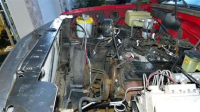
I ordered a new windshield washer tank & all hardware for a '98 Yukon; it's still available new from GM! The later trucks have it under the battery on the driver's side. My truck has it where my ECM is going to go... I also have the GM parts to move the battery over to the driver's side.

Next step is to drop the fuel tank, pressure wash the hell out of the underside, and POR15 coat the frame and anything else rusty under there. Doesn't look like it's too bad at all, just surface rust on the frame & the body looks clean.

---------- Post added at 11:05 AM ---------- Previous post was at 11:04 AM ----------

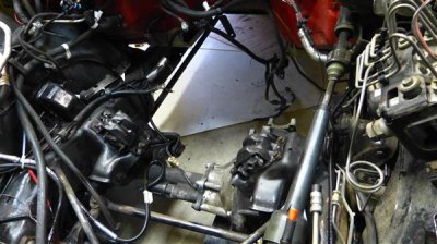
BTW, in the pic of the L94 & 6L80 the wood blocks are just a safety precaution. It all balances fine on that engine stand. Very nice piece!
 
OP
OP
N

Nak

Full Access Member
Joined
Aug 15, 2013
Posts
185
Reaction score
10
Now that the 700R4 is out I was able to take some good measurements. Both the 700R4 and the 6L80 are 26 7/8" long from forward mounting surface to the rear mounting surface of the 4WD adapter. As far as the mounting holes for the transmission mount, the distance from the center of those holes to the rear surface of the 4WD adapter is 2.5" on the 700R4 and 1.5" on the 6L80. So, the transmission crossmember will need to be moved 1" rearward. Pretty easy since it just bolts in place with 4 bolts. 4 new holes in the frame and all will be good. The driveshafts and TC shift linkage should line up perfectly. The shift shaft on the 6L80 is about an inch?? further rear than the 700R4. I think I'll be switching to cable linkage--I already have the IdidIt kit-- but I'm going to leave the rod linkage in place to see if it works. Even if it does, I'll probably need to switch to cable to make room for the exhaust.

Edited to add: OK, I measured the shifting shafts. From the front mating surface of the transmission to the center of the shifting shaft: 700R4 9"; 6L80 10.75"
 
Last edited:
OP
OP
N

Nak

Full Access Member
Joined
Aug 15, 2013
Posts
185
Reaction score
10
Just been treating rust and cleaning. I'll be coating the underside with POR15 today or tomorrow, then the modifications can begin. First on that front will be stripping the existing harness down to what is necessary: AC, lights, ABS, etc. None of that connects to the ECM on my year, so it'll be a matter of identifying and eliminating all of the wiring for the old ECM. I'll be leaving pigtails on all of the wires going in to the firewall connector for the ECM; that;ll leave a convenient and factory method of running wires in & out of the cab. Also, I'll start on fabricating a mount for my electric fans. They're factory 9 blade fans & shroud out of a 2009 Escalade.

My plans on oil & trans cooling is separate coolers with fluid flow controlled by a thermostat. Any thoughts on that?

---------- Post added at 11:14 AM ---------- Previous post was at 10:05 AM ----------

Yeah! Good news. I'm using the 1998 fuel tank because the fuel sender unit is compatible with the late model computers. It has a vapor pressure sensor in it, but is the wrong one for the L94. I got the proper one today, GM # 13502903, and it fits right in to the hole for the 1998 sensor. Perfect. I wasn't' sure they if they kept the size the same for the Gen IV stuff. Thank God for GM always keeping damn near everything compatible.
 
OP
OP
N

Nak

Full Access Member
Joined
Aug 15, 2013
Posts
185
Reaction score
10
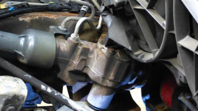
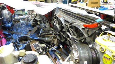
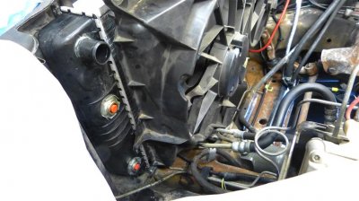
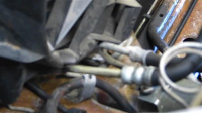
I put the radiator and electric fans in place to see how the fans would fit. Looks pretty good; shouldn't be too hard to install. I'll have to trim the shroud where it hits the steering box. Also, it sit's out about 3/8" on either side. I could trim the top and bottom to get it flush, but on the bottom I'd be trimming away part of the support for the lower mounts. On the plus side it would probably get it off the steering box. I could also just use foam strips to seal the sides. I'll decide on that later. Also, the power steering lines need to be bent out of the way.
 

Attachments

  • P1030591 (Small).JPG
    P1030591 (Small).JPG
    71 KB · Views: 82
  • P1030592 (Small) (Custom).JPG
    P1030592 (Small) (Custom).JPG
    70.7 KB · Views: 88
  • P1030593 (Small).JPG
    P1030593 (Small).JPG
    83.2 KB · Views: 76
  • P1030594 (Small).JPG
    P1030594 (Small).JPG
    53.9 KB · Views: 79
  • P1030595 (Small).JPG
    P1030595 (Small).JPG
    62.5 KB · Views: 81
OP
OP
N

Nak

Full Access Member
Joined
Aug 15, 2013
Posts
185
Reaction score
10
Here's the new motor mounts. The base of the mounts is convex and flattens out when torqued down. New to me, but apparently as designed.
 

Attachments

  • 0007 New Motor Mounts (Custom).JPG
    0007 New Motor Mounts (Custom).JPG
    63.9 KB · Views: 98
OP
OP
N

Nak

Full Access Member
Joined
Aug 15, 2013
Posts
185
Reaction score
10
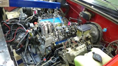
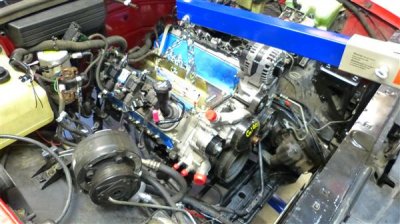
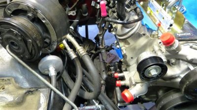
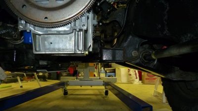
Got the L94 in and test fitted today! It's back out now, but I learned a lot doing this. First, my oil pan is fine as is. It's one inch higher than the suspension nearby and the front crossmember. It's three inches higher than the front Diff skid plate. One of these days I'll add a skid plate that covers both the Diff and the oil pan. Also, tons of clearance everywhere, except for one spot I'll talk about in my next post. More than enough room to install the exhaust manifolds after engine installation. Also, no need to remove most of the accessories to drop the engine in. The power steering pump is the exception. Pretty hard to get the motor mount through bolt in place with the PS pump in place.
 

Attachments

  • P1030596 (Custom).JPG
    P1030596 (Custom).JPG
    72.1 KB · Views: 91
  • P1030597 (Custom).JPG
    P1030597 (Custom).JPG
    69.8 KB · Views: 82
  • P1030598 (Custom).JPG
    P1030598 (Custom).JPG
    64.1 KB · Views: 86
  • P1030599 (Custom).JPG
    P1030599 (Custom).JPG
    67.9 KB · Views: 82
  • P1030601 (Custom).JPG
    P1030601 (Custom).JPG
    47.4 KB · Views: 91
OP
OP
N

Nak

Full Access Member
Joined
Aug 15, 2013
Posts
185
Reaction score
10
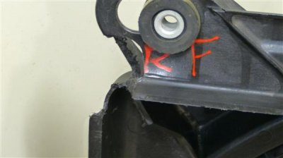
There is a boss that is damn close to the motor mount, maybe 1/8" at best. Also, a tab on the oil pan is awfully close, the tab right by the offending boss. I'm thinking of grinding about 1/4" of the boss and tab off. Is there any reason I shouldn't? There's no way it could ever be used considering where it is...

Close Boss 1 (Custom).JPG


Close Boss 2 (Custom).JPG


Close Boss 3 (Custom).JPG
 
OP
OP
N

Nak

Full Access Member
Joined
Aug 15, 2013
Posts
185
Reaction score
10
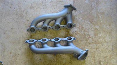
Got my exhaust manifolds back from being ceramic coated...
 

Attachments

  • Exhaust manifolds - Ceramic Coated (Custom).JPG
    Exhaust manifolds - Ceramic Coated (Custom).JPG
    48.7 KB · Views: 55
OP
OP
N

Nak

Full Access Member
Joined
Aug 15, 2013
Posts
185
Reaction score
10
Got the fan mounts done. I'll post pics of the fan shroud later, I had to chop it up a bit to make it fit. Most of that won't show though, should look pretty factory. BTW, the connectors for the motors are GM # 13580874 or ACDelco PT2649. $15 at Amazon.
 
OP
OP
N

Nak

Full Access Member
Joined
Aug 15, 2013
Posts
185
Reaction score
10
Thanks! Yeah, it should be almost too much fun! The 6l80 has roughly a 4:1 1st gear compared to the roughly 3:1 first with the 700R4. That makes my 3.73 gears the equivalent of 5.00's. :jawdrop: Combined with the ridiculously fat torque curve that the VVT gives you it should be quite the rocket sled. I'm actually worried that even with the Trutrac rear I might not be able to keep any kind of traction at full throttle. :burnout:
 
OP
OP
N

Nak

Full Access Member
Joined
Aug 15, 2013
Posts
185
Reaction score
10
Thanks Bowtie! That means a lot coming from the owner of arguably one of the best 2 doors anywhere! Love your truck man!

---------- Post added at 11:38 PM ---------- Previous post was at 10:44 PM ----------

Here's the Fan pics. This would be a great mod even for a Stock 350. I picked up a low mileage fan setup complete for $120 on eBay.

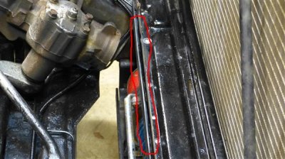
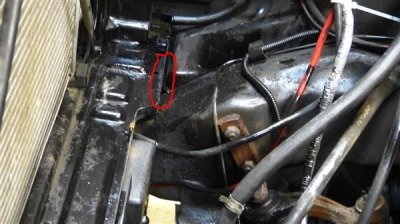
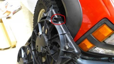
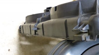
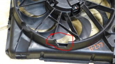
I trimmed the bottom down about 1/2" so that it was even with the ridge. Trim the top by the same amount the bottom was trimmed. I also had to remove the driver's side bottom mount; it interfered with the frame. You can see I trimmed the middle mount too. I had to notch the top on both sides to clear the top radiator supports. I cut off extensions on both the left and right side which left a hole, as you can see on the passenger side. I'll patch that later. Then I braced the bottom radiator support with 1/8" x 3" aluminum plate. Below that I mounted a 1/8" x 1.25" steel plate angle iron. That was mounted as to leave 3/8" clearance from the bottom radiator support. I stopped short of my winch control box on the passenger side. The extra wide portion of the bottom support circled in red matches up perfectly with the passenger side bottom mount on the fan shroud.

Later, I'll use a piece of sheet metal to complete the top mount. I'll clean up the cuts with some sandpaper; should look pretty factory when it's done, at least from the top. LOL

This works great! There'es a bit of space on the left and right side between the shroud and the radiator--about 3/8"--which I'll fill with heat resistant foam tape. Easy to put bolt up, easy to remove. Just slide the fan shroud down into the gap between the angle iron and the bottom radiator support, install bolts at top. Factory parts and lots of airflow.
 

Attachments

  • P1030611 (Custom).JPG
    P1030611 (Custom).JPG
    79.2 KB · Views: 70
  • P1030612 (Custom).JPG
    P1030612 (Custom).JPG
    74 KB · Views: 74
  • P1030613 (Custom).JPG
    P1030613 (Custom).JPG
    59.7 KB · Views: 79
  • P1030614 (Custom).JPG
    P1030614 (Custom).JPG
    35.5 KB · Views: 69
  • P1030616 (Custom).JPG
    P1030616 (Custom).JPG
    54.7 KB · Views: 63
Last edited:
OP
OP
N

Nak

Full Access Member
Joined
Aug 15, 2013
Posts
185
Reaction score
10
One more fan pic...
 

Attachments

  • P1030618 (Custom).JPG
    P1030618 (Custom).JPG
    34.3 KB · Views: 54
OP
OP
N

Nak

Full Access Member
Joined
Aug 15, 2013
Posts
185
Reaction score
10
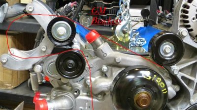
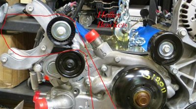
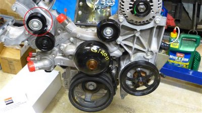
Got the Holley AC bracket on. Very nice; looks factory. There is one issue. If you look at the idler pulley I circled in red, you can see it is not needed. If you use all of the Holley LS brackets, the belt comes up to the top of the AC compressor from the water pump; so it is needed in that case. However, if you're only using the Holley AC bracket and the rest of the brackets are GM, the belt routes from under the upper right idler pulley to the top of the AC. The circled pulley actually hurts you in this case. It put's the belt closer to being up in the way, it reduces contact with the AC pulley and it adds one more pulley that can fail.

I haven't decided for sure yet, but I think I'll cut off the boss that holds the red circled pulley.
 

Attachments

  • GM Brackets (Custom).jpg
    GM Brackets (Custom).jpg
    57.1 KB · Views: 61
  • Holley Brakets (Custom).jpg
    Holley Brakets (Custom).jpg
    57.5 KB · Views: 63
  • Pulley (Custom).jpg
    Pulley (Custom).jpg
    54.7 KB · Views: 57

livingez_123

Full Access Member
Joined
Feb 18, 2013
Posts
1,799
Reaction score
114
Location
Sandy, OR
Holley didn't give you a belt routing diagram? I would call them before doing any cutting.
 

Forum statistics

Threads
138,117
Posts
1,999,574
Members
103,040
Latest member
CrackerJack135

Latest posts

Back
Top