
Hubs!?!?!??!?!?!

Disclaimer: Links on this page pointing to Amazon, eBay and other sites may include affiliate code. If you click them and make a purchase, we may earn a small commission.

Donnie Yukonie

Yates Caretaker
Joined
Jul 31, 2011
Posts
5,127
Reaction score
164
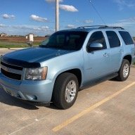
ok first lets do a brief history well for any that didnt know mmy yukon has seen more mud than a willys army jeep , and as a vetaran offroady i know that shit will break more often than not and you name it ive broken it .axle assy,hubs,shocks, transmissions,rear dif,tow hooks, rear sway bar<--dont know dont ask- but is it really nessacary that this will be the 7th yes SEVEN hub:emotions122: im going to replace in the last 2 years? ive tried the cheapys, GMs over priced 258 dollar ones , all lasting about the same amount of time i cant really afford a SAS all at once , is there somthing that makes these things wear out prematurley? a month ago i replaced pitman arm idler arm and ball joints thinking those worn parts had a role. is there somthing i missed?:fish_h4h:
 
OP
OP
Donnie Yukonie

Donnie Yukonie

Yates Caretaker
Joined
Jul 31, 2011
Posts
5,127
Reaction score
164
you wouldnt happen to know the spec would you had a shop do my last cv due to time crunch
 

SunlitComet

OBS Jedi-Do Good
Joined
Sep 30, 2010
Posts
16,206
Reaction score
188
Location
unknown at this time.
A whopping 165 Foot pounds.

Here is the whole procedure:


Front Drive Axle FRONT DRIVE AXLE


  • Tools Required:
  • J 24319-B Steering Linkage Puller
  • J 36605 Front Knuckle Seal Installer
  • J 36607 Upper Ball Joint Separator
  • J 29193 Steering Linkage Installer (12 mm)
REMOVE OR DISCONNECT


  • Raise vehicle and support it with safety stands.

  1. Wheel and tire assembly.

78844777


  • Insert a drift or large screwdriver through the brake caliper into one of the brake rotor vanes to prevent drive axle (halfshaft) from turning.

78263619


  1. Drive axle (halfshaft) hub nut (203) and washer (202).


  1. Wrap shop towels around both the inner and outer ON joint boots to avoid damage to the boots during removal and installation.

78844778


78844779


  1. Wheel speed sensor wire support bracket from upper control arm to allow extra travel of knuckle (all models). Also remove wire and brake line support brackets from knuckle on 8600# and heavier GVWR.
  2. Prevailing torque nut from outer tie rod. Do not reuse the nut.

78844780


  1. Separate the outer tie rod ball stud from the steering knuckle using J 24319-B. NOTICE: Do not disengage the joint by driving a wedge-type tool between the joint and the knuckle. This may cause seal damage.

    • Push linkage to opposite side of the vehicle and secure outer be rod up and out of the way. This will provide the needed clearance to remove the drive axle (halfshaft).

78844781


  1. Lower shock mounting nut and bolt.

    • Collapse the shock absorber and secure if necessary.

78263620


  1. Stabilizer shaft components as follows:

    • Remove stabilizer shaft bushing and bracket.
    • Remove stabilizer shaft bolt, spacer, and nut assembly at the lower control arm.
NOTICE: This is required on vehicles with 8050 lb. and below GVW rating to provide needed clearance for drive axle (halfshaft) removal.


  1. Position floor jack or stand behind the steering knuckle. CAUTION: The floor jack or stand must remain under the control arm while servicing the drive axle (halfshaft) to maintain torsion bar and control arm position. Failure to do so could result in personal injury .
  2. Cotter pin (138) from the upper control arm ball joint stud.

    • Loosen (do not remove at this time) the stud nut on the upper ball joint stud.
    • Loosen the stud from the knuckle using J 36607.

78844782


  1. Nut (139).
  2. Stud (137) from knuckle. Important: Cover the shock mounting bracket and the ball stud on the lower control arm with a shop towel to prevent possible drive axle (halfshaft) boot damage during removal and installation.
  3. Knuckle assembly using hammer and brass drift or equivalent to separate outer C/V joint splined shank from knuckle hub.
  4. Six bolts (200) from inboard joint flange.

    • Support inboard end of drive axle (halfshaft). Move knuckle and hub assembly outward to free splined shank from hub.

  1. Drive axle (halfshaft) from vehicle. Important: Wipe the wheel bearing seal area on the knuckle clean.
Inspect


  • Check the seal for cuts or tears.

  1. Lubricate the seal lip.

    • If seal is cut or torn, inspect the wheel bearing for damage and replace the seal.

  1. Replace the seal as follows:

    • Pry old seal from knuckle and discard.
    • Lubricate the new seal lip.
    • Use J 36605 to install the seal in the knuckle.
INSTALL OR CONNECT

NOTICE: Always use the correct fastener in the proper location. When you replace a fastener, use ONLY the exact part number for that application. The manufacturer will call out those fasteners that require a replacement after removal. The manufacturer will also call out the fasteners that require thread lockers or thread sealant. UNLESS OTHERWISE SPECIFIED, do not use supplemental coatings (paints, greases, or other corrosion inhibitors on threaded fasteners or fastener joint interfaces. Generally, such coatings adversely affect the fastener torque and joint clamping force, and may damage the fastener. When you install fasteners, use the correct tightening sequence and specifications. Following these instructions can help you avoid damage to parts and systems.


  • Prior to drive axle (halfshaft) installation, cover the shock mounting bracket, lower control arm ball stud, and all other sharp edges with shop towels so that drive axle (halfshaft) boot is not damaged during assembly.
Important: Do not lubricate the drive axle (halfshaft) splines and knuckle with grease.


  1. Insert outer C/V joint splined shank into knuckle hub and secure inboard C/V joint flange to companion flange with bolts. Do not tighten.
  2. Upper ball joint to the steering knuckle.
  3. Stud nut.

    • Tighten stud nut to 100 Nm (75 ft. lbs.) .

  1. Cotter pin.

    • Lubricate the upper ball joint until grease appears at the seal.

  1. Stabilizer shaft bushing (65) and bracket (64) and bolts (63).

    • Tighten bolts (63) to 33 Nm (24 ft. lbs.) .

  1. Stabilizer shaft link bolt assembly (62), spacer (56), and nut assembly (50).

    • Obtain torque by running nut assembly to the unthreaded portion of the bolt, then tighten to 18 Nm (13 ft. lbs.) .
    • Remove floor jack or stand from beneath lower control arm.

  1. Shock absorber to the lower shock mounting bracket.
  2. Shock mounting bolt washer and nut.

    • Tighten nut to 73 Nm (54 ft. lbs.) .

  1. Outer tie rod to steering knuckle using J 29193. Tighten tool to 54 Nm (40 ft. lbs.) .
  2. New outer tie rod prevailing torque nut.

    • Tighten nut to 62 Nm (46 ft. lbs.) .

  1. Brake pipe support bracket to the upper control arm.

    • Tighten nut to 17 Nm (13 ft. lbs.) .
Important: Make sure that the brake hose is not twisted or kinked, or damage to the hose could result.


  1. Hub nut washer (202) and nut (203). Seat shank splines in hub.
  2. Insert a drift through brake caliper to prevent drive axle (halfshaft) from turning.

    • Tighten inboard flange bolts to 78 Nm (58 ft. lbs.) .

  1. Hub nut.

    • Tighten hub nut to 225 Nm (165 ft. lbs.) .

  1. Remove drift and install wheels.
  2. Remove safety stands, and lower the vehicle.
 
OP
OP
Donnie Yukonie

Donnie Yukonie

Yates Caretaker
Joined
Jul 31, 2011
Posts
5,127
Reaction score
164
WOW! where did you get that my haynes manual is not that detailed?? you a tech at a shop? 5 STARS MAN THANKS:biggun:
 
OP
OP
Donnie Yukonie

Donnie Yukonie

Yates Caretaker
Joined
Jul 31, 2011
Posts
5,127
Reaction score
164
yea i did too a few years back its got some ok info but when it comes to doing the jobs sometimes its difficult because its not always clear or doesnt have a detailed picture of what your changing
 

Forum statistics

Threads
138,153
Posts
2,000,641
Members
103,079
Latest member
mfinta
Back
Top