Matthew Snyder
TYF Newbie
- Joined
- Jul 24, 2019
- Posts
- 15
- Reaction score
- 4
Hello everyone I am new to the site did some scavenging and found very useful information however have yet to find something pertaining to my exact situation so I hope this hasn't already been answered, if so I apologize.
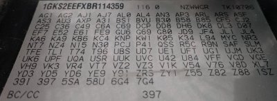
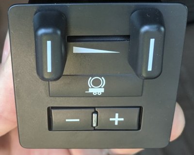
I have the factory integrated trailer brake on my 2011 GMC Yukon Denali with the Tow Package. After a brief investigation I have found the following..
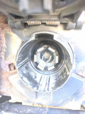
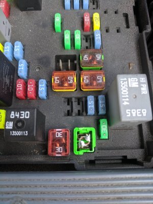
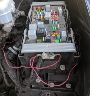
I have no DIC for gain adjustment when pressing + or - on the controller itself when connected to a trailer or not, after connecting to a trailer the DIC doesn't display "Trailer Connected" message, the fuses are good and installed (30a and 40a), I found one wire taped up and not connected beneath master brake cylinder under hood (it's my understanding this is to be run to Stud #2 on fuse box to apply 12v signal to trailer aux battery), I found another wire taped up and not connected to anything on driver side of fuse box (it's my understanding this is the power signal to the controller itself to be ran to Stud #1) there is currently a wire connected to Stud #1 on fuse block, all three wires in question are red with black stripe, both stud #1 & 2 have ~12v+ on on them. When I connect wires as I believed them to be connected I was able to get 12v between 1 o'clock (+) and 7 o'clock (-) pins on male trailer plug at bumper. Without connecting wires as described there was no signal on these pins. The lights have all been operational no problem. Going from 5 o'clock pin (brake signal) to 7 o'clock pin (-) I get a pulsating 3.5v to 0v.. (it's my understanding this is the module looking for a trailer to be connected), is this too high of a voltage? How much resistance is this looking for I have about 2 ohms on the trailer brake circuit with a tandem axle electric brake system.
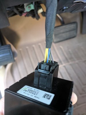
Does anyone know the required resistance for the truck to 'sense' a trailer so I could "mock" a connection with a resistor? Should I see some info on the DIC when pressing + or - on controller without a trailer connected? Does this seem like it could be the relay located beneath the spare tire on the truck, or perhaps the module? Maybe the controller in the dash itself? Have any of you experienced this before? What types of readings should I be seeing on the back side of the controller in the dash? Should the wires under the hood be connected in the fashion I described or am I missing something? I understand I should have some voltage at trailer brake pin that is how the truck recognized it's connected but 3.5v seems very high for that.. any assistance would be greatly appreciated.. I would think that the truck had never had the power wires connected under the hood I am left to believe this has never been used before therefore wouldn't understand why it shouldn't function now (aside from corrosion and poor connection) However I am not looking to dump hundreds of dollars into this to keep the ITBC I just think it would be nice over switching to an aftermarket on and skipping the hassle. I have been into the dealer and without turning it over to them which could be thousands in simply labor alone I am hoping to repair this myself otherwise will be installing aftermarket before our 3600 mile travel trailer towing journey and giving up with attempting to restore to its factory glory as I did with the autoride system.

