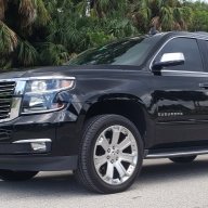
How to install GM 9L7 switches on a 2012 Tahoe, or any vehicle really.
Things you'll need:
The switches
A fuse box (got mine from ebay, but you can find cheaper on Aliexpress)
This connector (the black one): https://aliexpress.com/item/1005004426818768.html
Colored wires (20 awg is the maximum that fits in the connector)
Any type of connector (I got a cheap weather-pak set from Aliexpress)
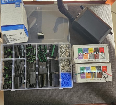
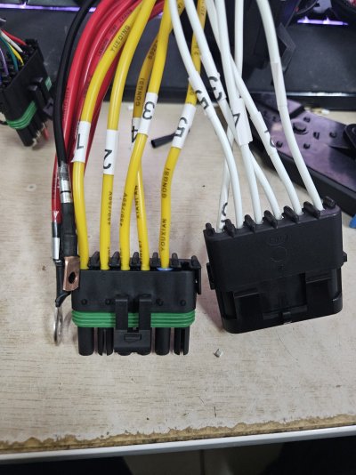
First thing we are going to do is make a harness that goes from the switches to two separate connectors, one for the fuse box, and one for the ground and backlight.
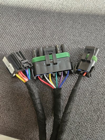
The connector to the switches will have 8 wires going into it, according to the diagram i found here https://www.coloradofans.com/thread...bution-box-and-5-switch-panel-install.451366/ "yellow" is for backlight (orange wire).
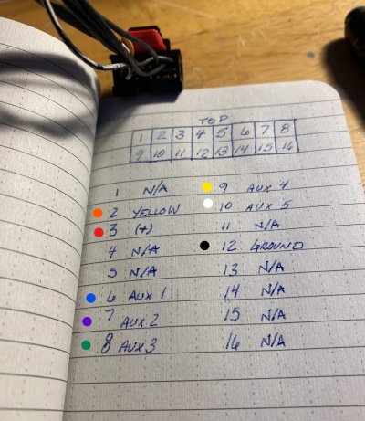
The fuse box connector will take the 5 outputs (white, yellow, green, purple, blue) from switches, but since the fuse box has 6 positions, we will use one of them (red) to power our switches, this way we get a fused wire going to the switches with the same connector (I used a 10 amp fuse).
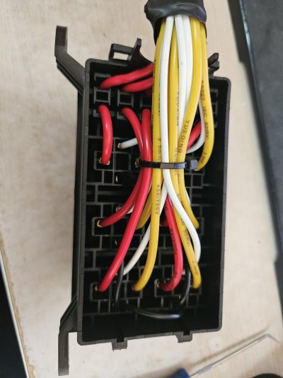
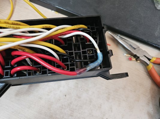
The last connector will have our ground which you can ground anywhere, and our backlight which I'm gonna tap into the traction control switch harness to take.
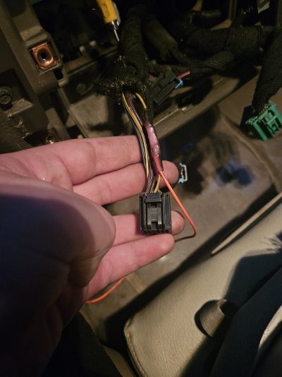
The lengths will vary depending on where you are going to place everything.
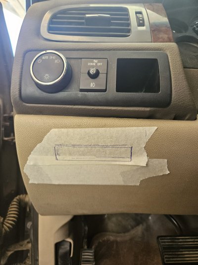
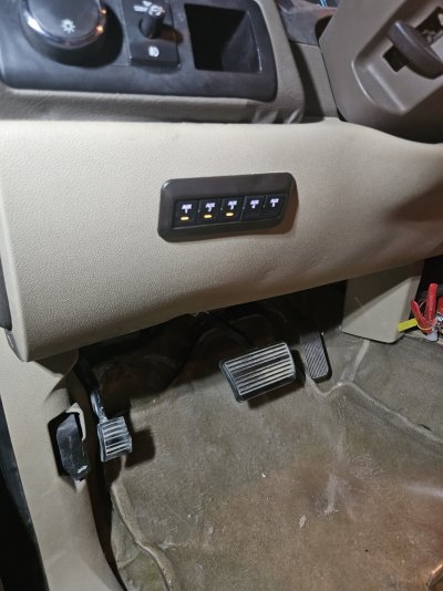
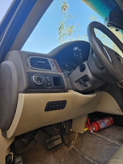
Next we are going to mount our switches, I'm gonna put them under the headlight switch where it's originally meant to go on the newer models.
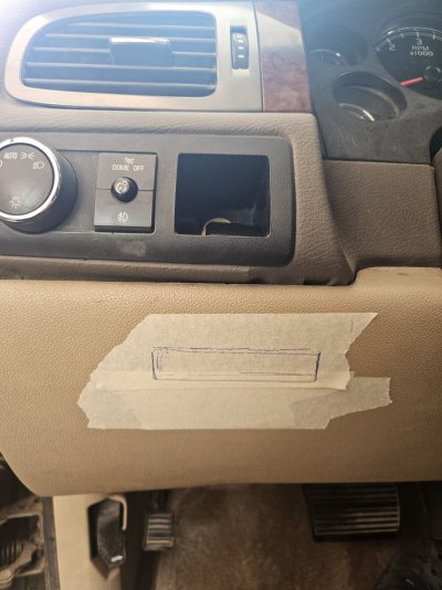
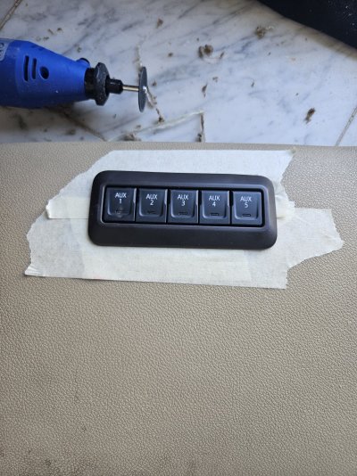
You will need to chew the dash a little to get it to fit .

Now feed the wire through.

Tap into the traction control switch for backlight, and ground the other wire.
Now let's get to the fuse box.
We are gonna have three connectors coming out of it, one for our signals from the switches + power to switch, one for the outputs of the relays (loads), and one for power which we are going to combine with the ground terminal that normally comes on the fuse box because the switches are what's going to give us the grounds.
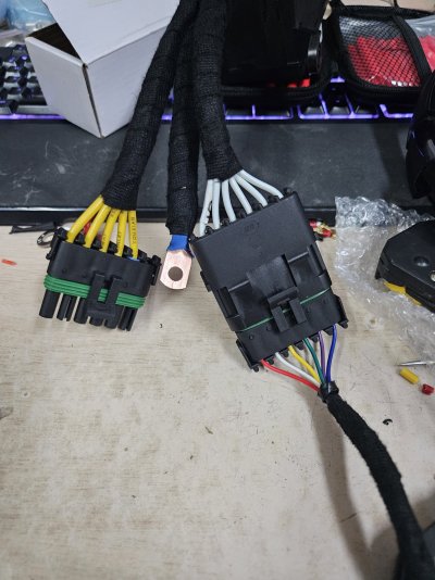
Now connect it to power and you should end up with this:
Things you'll need:
The switches
A fuse box (got mine from ebay, but you can find cheaper on Aliexpress)
This connector (the black one): https://aliexpress.com/item/1005004426818768.html
Colored wires (20 awg is the maximum that fits in the connector)
Any type of connector (I got a cheap weather-pak set from Aliexpress)
First thing we are going to do is make a harness that goes from the switches to two separate connectors, one for the fuse box, and one for the ground and backlight.
The connector to the switches will have 8 wires going into it, according to the diagram i found here https://www.coloradofans.com/thread...bution-box-and-5-switch-panel-install.451366/ "yellow" is for backlight (orange wire).
The fuse box connector will take the 5 outputs (white, yellow, green, purple, blue) from switches, but since the fuse box has 6 positions, we will use one of them (red) to power our switches, this way we get a fused wire going to the switches with the same connector (I used a 10 amp fuse).
The last connector will have our ground which you can ground anywhere, and our backlight which I'm gonna tap into the traction control switch harness to take.
The lengths will vary depending on where you are going to place everything.
Next we are going to mount our switches, I'm gonna put them under the headlight switch where it's originally meant to go on the newer models.
You will need to chew the dash a little to get it to fit .
Now feed the wire through.
Tap into the traction control switch for backlight, and ground the other wire.
Now let's get to the fuse box.
We are gonna have three connectors coming out of it, one for our signals from the switches + power to switch, one for the outputs of the relays (loads), and one for power which we are going to combine with the ground terminal that normally comes on the fuse box because the switches are what's going to give us the grounds.
Now connect it to power and you should end up with this: