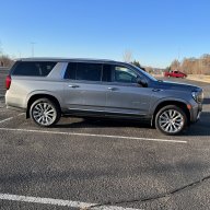
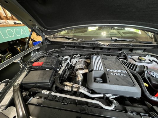
Adding 12v to back end of 23 Yukon Denali

Disclaimer: Links on this page pointing to Amazon, eBay and other sites may include affiliate code. If you click them and make a purchase, we may earn a small commission.

BobHolthaus

Member
Joined
May 2, 2023
Posts
97
Reaction score
57
My girlfriend took delivery of her 2023 Denali Duramax 2 weeks ago and I am shocked that there is no 12v outlet in the cargo area. We both run ARB Fridges in our vehicles; can someone point me to a thread or tell me the easiest way to route wiring back there for an outlet? I’m a Jeep guy, so I can wire just about anything (I own a low voltage company). But I’d love some advice on where to run wiring and if there is anywhere to tap 12v constant other than the battery. Thanks in advance.
 

Doubeleive

Wes
Supporting Member
Joined
Nov 7, 2017
Posts
30,747
Reaction score
48,433
Location
Stockton, Ca.
does it have a tow package? if so there is 12v right there, might have to connect the wire up front under the hood typically in the past generations it's bundled up somewhere near the fuse box or battery and connects to a post/terminal. if you can't find it swing by any trailer store that installs tow packages they should know right where it is.

once you patch into 12v you should be able to remove a tail light housing and run it inside from behind the tail light
 

Mean_Green

Full Access Member
Joined
Mar 23, 2023
Posts
473
Reaction score
594
^^^ I did that on my '98. Used the 12V from the tow harness, drilled a small hole in the floor under the left compartment where the jack is stowed and put a 4 terminal fuse block in there.
 
OP
OP
BobHolthaus

BobHolthaus

Member
Joined
May 2, 2023
Posts
97
Reaction score
57
Ah yes, this is why I lean into these forums! The 12v from the tow package is a great idea, and it should be independently fused as well. Thank you guys. I’ll try to figure it out and post back here when I’m finished.
 
OP
OP
BobHolthaus

BobHolthaus

Member
Joined
May 2, 2023
Posts
97
Reaction score
57
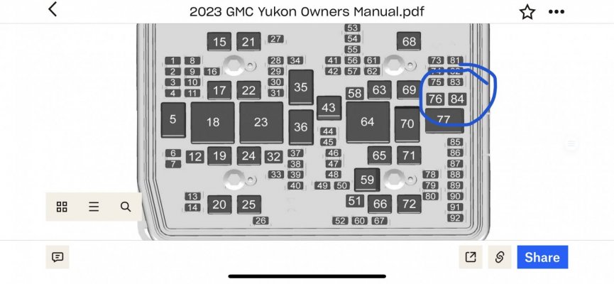
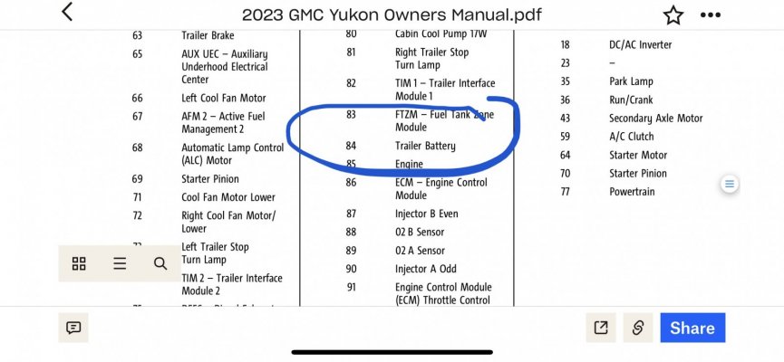
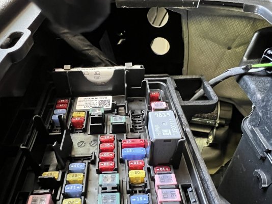
I will verify this with my 12v tester, but based upon the owners manual, this should be fuse 84.
 

Attachments

  • IMG_8120.jpeg
    IMG_8120.jpeg
    130.2 KB · Views: 44
  • IMG_8121.jpeg
    IMG_8121.jpeg
    124.5 KB · Views: 49
OP
OP
BobHolthaus

BobHolthaus

Member
Joined
May 2, 2023
Posts
97
Reaction score
57
Also, can anyone point me to a thread about removing the rear side panels so that I can flush mount an outlet? TIA.
 

StephenPT

Full Access Member
Joined
Jan 16, 2022
Posts
1,252
Reaction score
1,268
Location
St. Helens, OR
Here's the Body Builder Manual for your rig - lots of helpful info in here regarding wiring diagrams, functions, etc.


As far as removing a side panel - it's a pretty big job to completely remove the panel as you have to unbolt the end of the seatbelt from the floor and push it back through the panel to then remove the panel. You can however loosen the panel quite a bit and get decent access to the backside of it.

First remove the rear cargo sill. It's held down by metal clips, so you'll need a plastic trim tool to pry at a corner and once a couple of the clips release you can keep pulling to remove it completely. Next, lift the cargo compartment lid and you'll see four large plastic nuts holding the compartment to the floor. Remove those nuts and then the compartment lifts right out of the rig.

Next, remove the D-Pillar plastic trim. The first piece without the speaker grille needs to come off and then the piece with the speaker grille is held on by one 7mm head screw and a few metal clips. With that trim removed, take off the plastic nut used for the cargo net and below it the metal D-ring. Now you'll have access to pull the side panel away from the sidewall and have access to the backside. Good luck!

 
OP
OP
BobHolthaus

BobHolthaus

Member
Joined
May 2, 2023
Posts
97
Reaction score
57
Here's the Body Builder Manual for your rig - lots of helpful info in here regarding wiring diagrams, functions, etc.


As far as removing a side panel - it's a pretty big job to completely remove the panel as you have to unbolt the end of the seatbelt from the floor and push it back through the panel to then remove the panel. You can however loosen the panel quite a bit and get decent access to the backside of it.

First remove the rear cargo sill. It's held down by metal clips, so you'll need a plastic trim tool to pry at a corner and once a couple of the clips release you can keep pulling to remove it completely. Next, lift the cargo compartment lid and you'll see four large plastic nuts holding the compartment to the floor. Remove those nuts and then the compartment lifts right out of the rig.

Next, remove the D-Pillar plastic trim. The first piece without the speaker grille needs to come off and then the piece with the speaker grille is held on by one 7mm head screw and a few metal clips. With that trim removed, take off the plastic nut used for the cargo net and below it the metal D-ring. Now you'll have access to pull the side panel away from the sidewall and have access to the backside. Good luck!
Wow, this does seem like quite a project. Thank you for the PDF; I looked at the trailering section and am immediately reminded that every wire on these things seems to run through the CANBUS system (or whatever GMC calls it). It says the trailer battery connector is "constant" (page 2-60), but that the vehicle may not allow certain accessories to function. It would be a shame if the car was so "smart" that it turned off the circuit to my 12v outlet, which would be powering the ARB Fridge unit. I am quickly thinking that it may be in my best interest to run an appropriate wire directly to the battery that cannot be shut off accidentally. THIS is the kit I have used in the past on my Jeeps.
 
OP
OP
BobHolthaus

BobHolthaus

Member
Joined
May 2, 2023
Posts
97
Reaction score
57
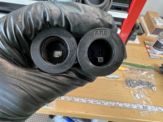
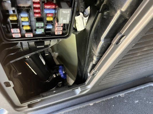
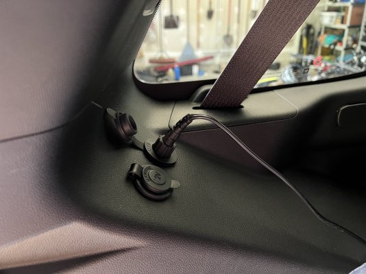
Okay, after looking at the backend tonight, I didn’t realize there was a fuse box behind a panel on the driver side. That allows me to reach my hand up and touch the plastic above it. I am going to install Two 12 V outlets facing up back there, one which will be a regular outlet and the other one will be an ARB locking outlet. I bought THIS wiring kit from ARB and will drill a hole down in the bottom of that cubby near the bottom of the jack and will run the wire up underneath the car all the way to the battery. It should be very simple. I will post pics when I’m finished.
 

Mean_Green

Full Access Member
Joined
Mar 23, 2023
Posts
473
Reaction score
594
'You'll put your battery out with that thing!!'

Be careful that whatever you plug in back there doesn't have the ability to run your battery down. Most stock things are run through some sort of timer that kills power after a few minutes.

.
 
OP
OP
BobHolthaus

BobHolthaus

Member
Joined
May 2, 2023
Posts
97
Reaction score
57
'You'll put your battery out with that thing!!'

Be careful that whatever you plug in back there doesn't have the ability to run your battery down. Most stock things are run through some sort of timer that kills power after a few minutes.

.
Yes, that’s exactly my concern trying to tap any OEM wiring or fuses, that the computer will prematurely shut the circuit down and the fridge will turn off. That’s why I’m not going to run a fresh, properly gauged wire with inline fuse directly to the battery, bypassing all internal ORM systems. I think that’s my safest bet to run a fridge freezer (which we don’t do daily, but probably at least once a week). Thanks for that reminder!!
 
OP
OP
BobHolthaus

BobHolthaus

Member
Joined
May 2, 2023
Posts
97
Reaction score
57
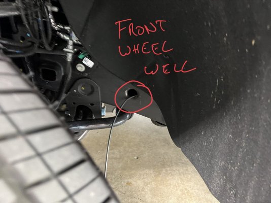
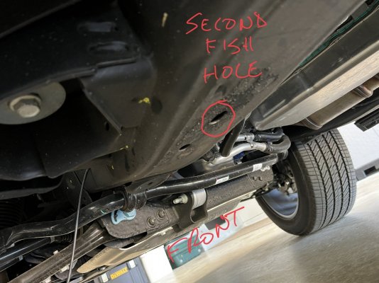
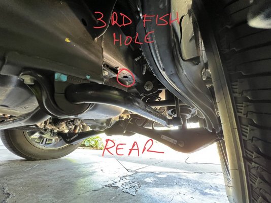
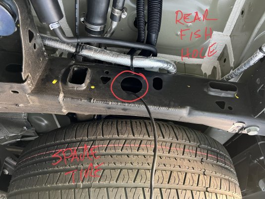
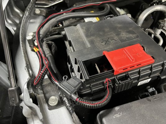
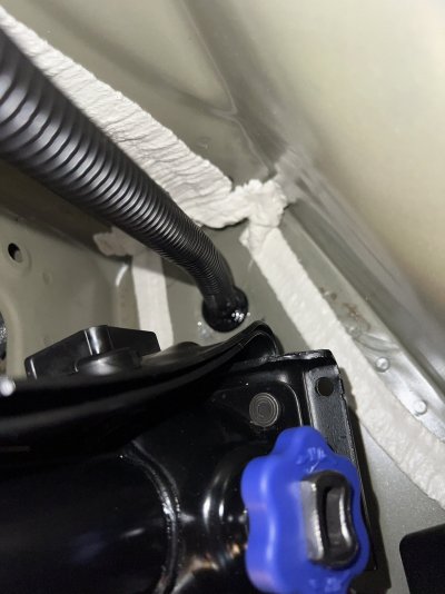
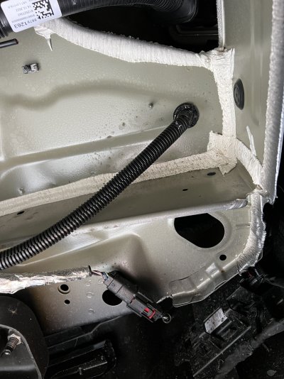
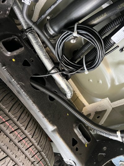
Okay, I started this project today. Spent 3 hours on it, only to realize that the 20’ of 10 gauge wire that comes with the ARB kit is too short. You need about 25’ of wire; I will use Molex Perma-Seal connectors to extend my wire. I’ll post when it’s all finished, but I fished the wire all the way from front to back through the main frame rail. This is an easy install, with a dedicated 15 amp fuse coming right off the battery. Let me know what questions you may have from my pics.

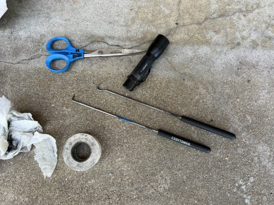
I’m running two 12v outlets, a standard outlet, and an ARB locking outlet. They will be wired in series. The wire is 10 gauge but I had hoped the 20 feet with the $58 ARB kit was enough. Btw, 10 gauge wire can handle 30 amps, and to be safe, you typically want to stay at 80% of that 24 amps). A 25 amp fuse is good for the circuit, witha 5 amp margin before a wire melts and starts on fire. I had to fish using 3 holes in the frame rail, but it worked great. Caution: that frame rail is full of black goopy stuff; be prepared to clean your fish tape and wear protective gloves. I showed the hook tools I used to get my fish tape out of those holes. I used 18 gauge as my fish wire; I’m likely going to leave it in the frame when finished in case I want to run anything else from front to back (like aux LED reverse lights!)

What else can I tell you? More pics when I finish. My 20’ of wire ended at the rear frame opening, where I will lengthen it. Doing it again I’d just get 28’ of 10 gauge wire and put it in flex loom (although fishing the one single 2 conductor wire made it easier).
 

Attachments

  • IMG_8226.jpeg
    IMG_8226.jpeg
    308.7 KB · Views: 54
  • 2E5B7D58-7D6D-4BFF-A9D7-7DEC78FDC34E.jpeg
    2E5B7D58-7D6D-4BFF-A9D7-7DEC78FDC34E.jpeg
    273.8 KB · Views: 57
  • F936F73D-7446-48D5-986A-CE3BDDA5EA36.jpeg
    F936F73D-7446-48D5-986A-CE3BDDA5EA36.jpeg
    290.9 KB · Views: 58
  • 5A39F91B-B405-4D3F-A29C-A45EF5CCC21F.jpeg
    5A39F91B-B405-4D3F-A29C-A45EF5CCC21F.jpeg
    354.9 KB · Views: 60
  • 90FED671-A150-4966-BEC5-473DA0A93D28.jpeg
    90FED671-A150-4966-BEC5-473DA0A93D28.jpeg
    408.9 KB · Views: 52
Last edited:
OP
OP
BobHolthaus

BobHolthaus

Member
Joined
May 2, 2023
Posts
97
Reaction score
57
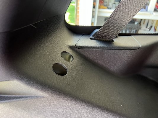
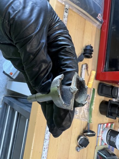
That’s a view looking up from rear fuse box. Used a 1 1/8” bit for the two holes. My wire will go out the bottom of that area at the bottom of the jack, through a rubber grommet (may go out the side if I can get to it with a drill bit, so the water from the tire isn’t splashing directly at the hole I’ll drill).

(Why can I only post 5 pics at a time?)
 

Attachments

  • IMG_8231.jpeg
    IMG_8231.jpeg
    358.9 KB · Views: 48
  • IMG_8230.jpeg
    IMG_8230.jpeg
    304.6 KB · Views: 40
  • IMG_8229.jpeg
    IMG_8229.jpeg
    338.5 KB · Views: 45
  • IMG_8228.jpeg
    IMG_8228.jpeg
    271.2 KB · Views: 45
  • IMG_8224.jpeg
    IMG_8224.jpeg
    807.2 KB · Views: 45
OP
OP
BobHolthaus

BobHolthaus

Member
Joined
May 2, 2023
Posts
97
Reaction score
57
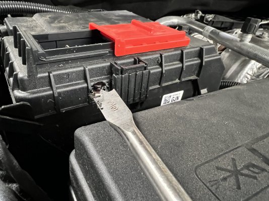
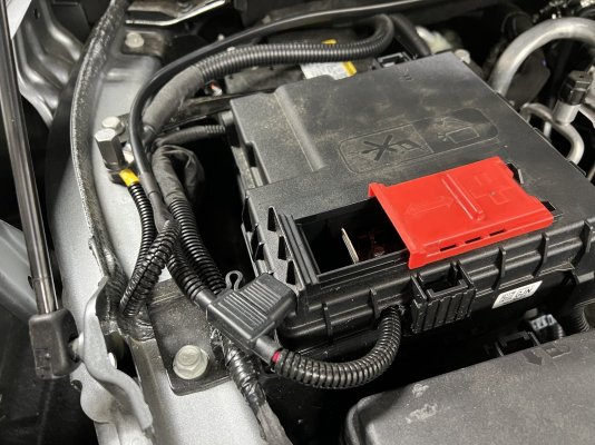
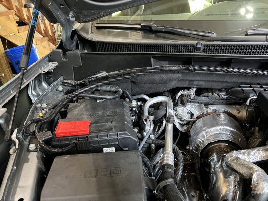
Pic of the fuse box where I drilled a hole in the cover to feed the positive wire in. Negative went to stud on fender. Then covered it with flex loom. Sorry, I forgot to take pics of it fed across the engine bay. I’ll post those when I finish the project this week.
 

Attachments

  • IMG_8233.jpeg
    IMG_8233.jpeg
    373.5 KB · Views: 42
  • IMG_8234.jpeg
    IMG_8234.jpeg
    379.9 KB · Views: 50
  • 4AB5D309-25B7-4538-9B39-30C6D8956D3F.jpeg
    4AB5D309-25B7-4538-9B39-30C6D8956D3F.jpeg
    381.4 KB · Views: 42
Last edited:
OP
OP
BobHolthaus

BobHolthaus

Member
Joined
May 2, 2023
Posts
97
Reaction score
57
Did you run the wire in wire loom all the way back, or do you just have a 12V wire w/ only insulation laying inside the frame?
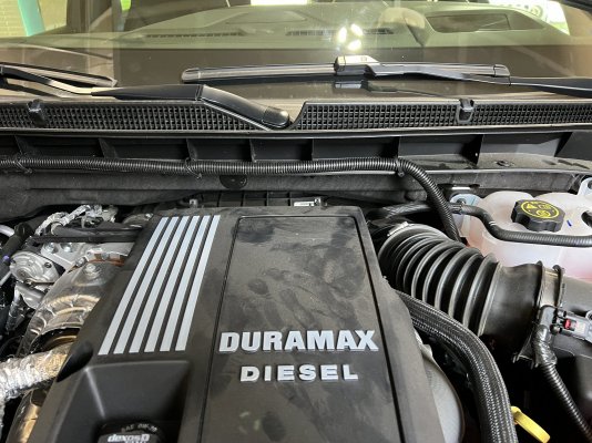
I only used loom at the front end and at the back end, where it came out of the frame. Up front I ran loom from the frame all the way to the battery, to make it look good. My conductors are individually sheathed, and then both are sheathed in another layer of covering, which I recommend,so it’s double sheathed (the look being the third layer from the copper). Inside the frame shouldn’t be an issue. All things considered, if you have enough loom (I didn’t), you might as well wrap it the entire length. There should be no tight space limitations inside the frame. I had some similar wire inside the frame of my Jeep JK for 10 years with no issues. But make sure you have a fuse as close to your battery as possible.
 
Last edited:
OP
OP
BobHolthaus

BobHolthaus

Member
Joined
May 2, 2023
Posts
97
Reaction score
57
And sorry, I finished the project but forgot to post pics. I will tomorrow. I ran my loom right across the top of the engine bay, below the windshield. I drilled holes in those verticle pieces of plastic at the top of the engine bay and used zip ties.
 
OP
OP
BobHolthaus

BobHolthaus

Member
Joined
May 2, 2023
Posts
97
Reaction score
57
More pics
 

Attachments

  • IMG_8390.jpeg
    IMG_8390.jpeg
    310.4 KB · Views: 51
  • IMG_8392.jpeg
    IMG_8392.jpeg
    218.9 KB · Views: 49
  • IMG_8393.jpeg
    IMG_8393.jpeg
    350.1 KB · Views: 51
  • IMG_8394.jpeg
    IMG_8394.jpeg
    425.3 KB · Views: 46
  • IMG_8395.jpeg
    IMG_8395.jpeg
    427.5 KB · Views: 47
OP
OP
BobHolthaus

BobHolthaus

Member
Joined
May 2, 2023
Posts
97
Reaction score
57
More pics. How do I get past the 5 pic limit?!
 

Attachments

  • IMG_8396.jpeg
    IMG_8396.jpeg
    417.1 KB · Views: 40
  • IMG_8397.jpeg
    IMG_8397.jpeg
    364.8 KB · Views: 33
Back
Top