TwiztidPixel
Full Access Member
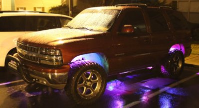
I've been asked a couple of times how I installed my rock lights. I have never written a HOWTO before, so if there is anything you think should be added, explained more or would like a photo of something, please ask. In case it needs to be said, I will link the products I used but I have no affiliation whatsoever.
The install isn't super difficult, it just takes time and a game plan. I hope the photos are understandable, I had to switch from my DSLR to my phone in some spots. Again, you are welcome to ask if you need a better photo of something.
FYI:
Even with my 33" tires, I was able to get my drill up into each wheel well after raising the corner with a jack. You should not have to remove any wheels for this.
As will be mentioned below, I needed 3 extensions cables, these will be for the two rear and the second from the rear on the passenger side.
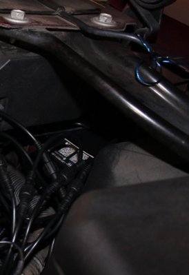
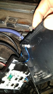
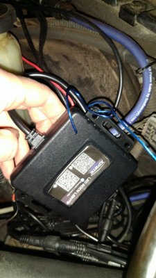
Also possibly important, I situated my "box" at the driver-side firewall, under the hood, so everything I say will be according to that location.
The actual products I used were:
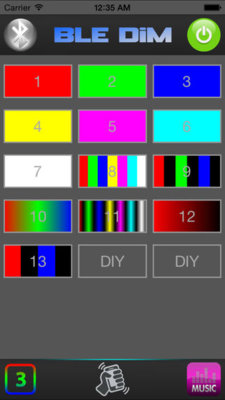
-Xprite 3rd-Gen rock light kit (8 pods)
https://www.amazon.com/gp/product/B01KGYQ5IU/ref=oh_aui_detailpage_o07_s00?ie=UTF8&psc=1
-Rock light extensions (I ordered 4 and needed 3, they're cheap enough you might as well get an extra just in case)
https://www.amazon.com/gp/product/B01L0ZXO60/ref=oh_aui_detailpage_o04_s00?ie=UTF8&psc=1
-I also used an inline fuse holder and a 15 amp fuse. (Auto parts store)
Tools and extra items needed:
-Stubby Phillips screwdriver
-Drill and bit for pilot holes (I used 3/32") **Get yourself at least 6 bits, I broke a few**
-#6 Metal screws (3/4" and 1") **I chose Phillips head to avoid the risk of a socket not fitting against the pod housing**
-1/4" coaxial clamps (Lowes has 20-packs, this is plenty)
-Zipties
-OPTIONAL: About 1 foot of thin wire, small butt connector, electrical tape, hot glue gun, 3mm allen driver
How I installed my lights:
I chose to start at the rear of the truck, knowing that would be the most ridiculous to run the cables. This kit gives you the option of running your cable straight up out of the back of the pod, or out of the side. I chose to run it out of the side as I can't imagine trying to fish that cable inside of the body.
In the rear wells there is a seam, I chose to mount my pods right behind that seam, so that it is not visible. My other reason for this is that I offroad frequently and my tires have not managed to hit this seam, so the pod should also be safe here.
The pods are where you'll use the longer of the screws. The rubber spacer that sits behind the pod take up more length than you might think.
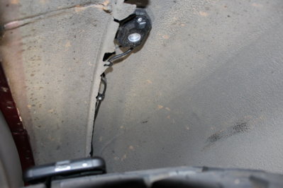
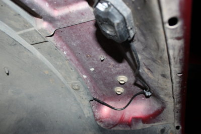
As you can see, the cable is routed outside of the pod instead of up into the body. You can also already see where the coaxial clamps will come into play.
Here is a better shot at my use of the coaxial clamps. This is where the shorter screws will be used (the clamps come with long screws as they're meant to be used on the outside of a building).
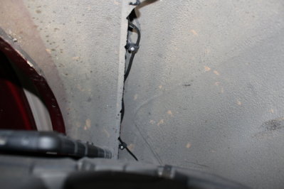
From here, there is a plastic liner towards the front of the well, you can use that separation to run your cable. (If you've replaced your own rear shocks, this is the cover that is in the way of the top nut, we're just working with the other end of it here.)

From here, it's just running the cable to the front of the vehicle. Run the cables along the frame. You will have some excess, and you will have even more as you mount the pods further forward. Just find a safe spot to ziptie them up. Obviously, don't ziptie them to anything that moves.
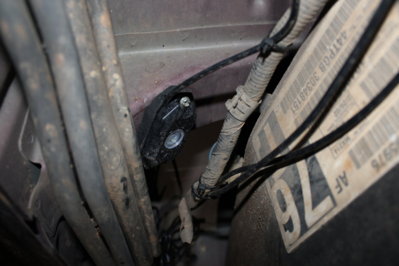
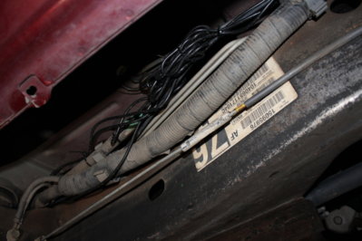
The two "middle" pods on each side were the hardest part. This is because there aren't many places that are identical on both sides, important for uniformity. The spots that are identical, and accessible, are still at an angle and much harder metal than the wheel wells. This is where you will break some drill bits.
Here is where I mounted mine:
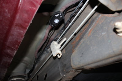
Second from the rear: *You can see where I'm running my cables along with the factory wire loom
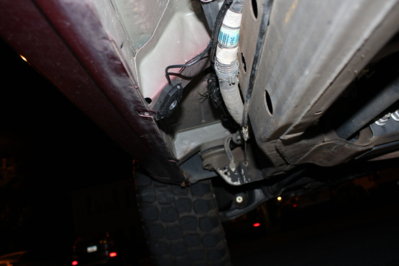
Closest to the front:
The install isn't super difficult, it just takes time and a game plan. I hope the photos are understandable, I had to switch from my DSLR to my phone in some spots. Again, you are welcome to ask if you need a better photo of something.
FYI:
Even with my 33" tires, I was able to get my drill up into each wheel well after raising the corner with a jack. You should not have to remove any wheels for this.
As will be mentioned below, I needed 3 extensions cables, these will be for the two rear and the second from the rear on the passenger side.
Also possibly important, I situated my "box" at the driver-side firewall, under the hood, so everything I say will be according to that location.
The actual products I used were:
-Xprite 3rd-Gen rock light kit (8 pods)
https://www.amazon.com/gp/product/B01KGYQ5IU/ref=oh_aui_detailpage_o07_s00?ie=UTF8&psc=1
-Rock light extensions (I ordered 4 and needed 3, they're cheap enough you might as well get an extra just in case)
https://www.amazon.com/gp/product/B01L0ZXO60/ref=oh_aui_detailpage_o04_s00?ie=UTF8&psc=1
-I also used an inline fuse holder and a 15 amp fuse. (Auto parts store)
Tools and extra items needed:
-Stubby Phillips screwdriver
-Drill and bit for pilot holes (I used 3/32") **Get yourself at least 6 bits, I broke a few**
-#6 Metal screws (3/4" and 1") **I chose Phillips head to avoid the risk of a socket not fitting against the pod housing**
-1/4" coaxial clamps (Lowes has 20-packs, this is plenty)
-Zipties
-OPTIONAL: About 1 foot of thin wire, small butt connector, electrical tape, hot glue gun, 3mm allen driver
How I installed my lights:
I chose to start at the rear of the truck, knowing that would be the most ridiculous to run the cables. This kit gives you the option of running your cable straight up out of the back of the pod, or out of the side. I chose to run it out of the side as I can't imagine trying to fish that cable inside of the body.
In the rear wells there is a seam, I chose to mount my pods right behind that seam, so that it is not visible. My other reason for this is that I offroad frequently and my tires have not managed to hit this seam, so the pod should also be safe here.
The pods are where you'll use the longer of the screws. The rubber spacer that sits behind the pod take up more length than you might think.

As you can see, the cable is routed outside of the pod instead of up into the body. You can also already see where the coaxial clamps will come into play.
Here is a better shot at my use of the coaxial clamps. This is where the shorter screws will be used (the clamps come with long screws as they're meant to be used on the outside of a building).

From here, there is a plastic liner towards the front of the well, you can use that separation to run your cable. (If you've replaced your own rear shocks, this is the cover that is in the way of the top nut, we're just working with the other end of it here.)

From here, it's just running the cable to the front of the vehicle. Run the cables along the frame. You will have some excess, and you will have even more as you mount the pods further forward. Just find a safe spot to ziptie them up. Obviously, don't ziptie them to anything that moves.
The two "middle" pods on each side were the hardest part. This is because there aren't many places that are identical on both sides, important for uniformity. The spots that are identical, and accessible, are still at an angle and much harder metal than the wheel wells. This is where you will break some drill bits.
Here is where I mounted mine:
Second from the rear: *You can see where I'm running my cables along with the factory wire loom

Closest to the front:

Last edited:

