Wiring Diagram for Electric Fans

Disclaimer: Links on this page pointing to Amazon, eBay and other sites may include affiliate code. If you click them and make a purchase, we may earn a small commission.

78mc-bbc

Member
Joined
Feb 7, 2011
Posts
76
Reaction score
0
Location
Harrisville, RI
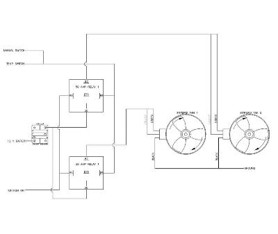
So i am trying to come up with an easy to follow diagram for adding a set of the intrepid fans to a car with a realy for each fan. After researching other's attempts at this online i came up with this below. Can someone more versed in wiring take a look and let me know if this looks like it will work???

DualRelaysForDualFans.gif
 
OP
OP
78mc-bbc

78mc-bbc

Member
Joined
Feb 7, 2011
Posts
76
Reaction score
0
Location
Harrisville, RI
The dodge intrepid fans are notorious for pulling 25 amps per fan, so i figure split the load to two relays. the fans also have two power lines they are wired strange, to get high you have to power the green and yellow wires, to get low speed you can power either the yellow or green
 

retorq

Full Access Member
Joined
Mar 4, 2010
Posts
3,018
Reaction score
10
Location
Kingman AZ
Honestly man I would just go with std fans, nothing fancy. Seems the guys that go all out run into issues reinventing something that should be simple. :D
 

SunlitComet

OBS Jedi-Do Good
Joined
Sep 30, 2010
Posts
16,206
Reaction score
184
Location
unknown at this time.
Wont work the relay on the bottom is miswired. Wire it exactly as the upper one and get rid if the upper relay 87a terminal powering the lower relay. As I see it currently as soon as the temp switch activate it will start the right fan but the left fan is immediately disabled. And the left won't work unless the temp switch grounds at which point the upper relay activates and disables the lower relay anyway. No fires or anything just only fan will go of into high power while the lower sits there. I would suggest using one relay for both fans at one power lead each for low speed on each and perhaps the other relay for the high speed on both for an A/C trigger.
 
OP
OP
78mc-bbc

78mc-bbc

Member
Joined
Feb 7, 2011
Posts
76
Reaction score
0
Location
Harrisville, RI
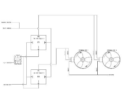
After talking to the guys over at 12Volt i came up with this approved schematic
DualRelaysForDualFans-Model.jpg
 
Last edited:

99Yuk

Full Access Member
Joined
Sep 28, 2009
Posts
1,080
Reaction score
13
Location
Northern Ontario, Canada
I know I'm a bit late to the party, but as I see it nothing will happen cuz the relay control coils are not grounded. I see two 12v inputs on each relay and no grounds. IGN on 86 is 12v and Manual/Temp switch on 85 is also 12v? Unless they are switched to ground...then it would work.

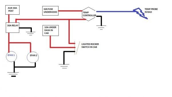
This is the wiring that I used on my setup...(homemade 'art' alert)
You could easily add another relay for the second fan.
picture.jpg
picture.jpg

IDK just my $0.02
 
OP
OP
78mc-bbc

78mc-bbc

Member
Joined
Feb 7, 2011
Posts
76
Reaction score
0
Location
Harrisville, RI
from talking to the guys at 12v, the temp switch or manual switch is the ground for the relays, so it will work
DualRelaysForDualFans-Model.jpg
 

Forum statistics

Threads
129,220
Posts
1,812,338
Members
92,321
Latest member
rick3645
Top