1995 Tahoe 6.5 diesel rear end problems In & out play on the passenger side. When rot

Disclaimer: Links on this page pointing to Amazon, eBay and other sites may include affiliate code. If you click them and make a purchase, we may earn a small commission.

jrsavoie

Member
Joined
Jul 24, 2010
Posts
47
Reaction score
0
Location
Illinois
1995 Tahoe 6.5 diesel rear end problems In & out play on the passenger side. When rot
1995 2 door Tahoe 6.5 diesel

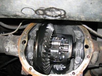
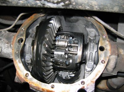
There is about 1/8" In & out play on the rear axle on the passenger side.

When rotating the axle about 1/4 turn at a time the axle will lock up. If you back it off it will go back to spinning free.

The pinion seems good, with no play.

I won't have time to take the cover off til next week or until it warms up some.

Any guesses as to what I will be looking at? Best case scenario?

We just recently had the cover off and changed the oil. There were no chips or shiny stuff in the oil we drained. We never noticed any problems with the axle when we put rear brakes on a couple weeks or so ago.

Immediately after that the Tahoe was driven to town and back with the emergency brake on. I don't know that this had anything to do with anything.

Are the rear ends for 2 door Tahoes specific to 2 door Tahoes? Or could the rear end out of a 4 door Tahoe or some other truck or Suburban be used?

What are my options there?

The same with the front differential? Which vehicles could I use a front differential out of?

I was thinking of switching from my 3.73 gears to 3.42 gears. Just swapping complete rear end and front differential.

Does anybody have any good links to working on this rear end?
 

SunlitComet

OBS Jedi-Do Good
Joined
Sep 30, 2010
Posts
16,206
Reaction score
188
Location
unknown at this time.
in out play normal. is this locking up make everything else move? get your cover off and inspect it. and leave the axle ratio the same. most case front and back diffy's are the same 2 or 4 dr.

---------- Post added at 06:26 PM ---------- Previous post was at 06:24 PM ----------

is this actually effecting driving.
 
OP
OP
J

jrsavoie

Member
Joined
Jul 24, 2010
Posts
47
Reaction score
0
Location
Illinois
in out play normal. is this locking up make everything else move? get your cover off and inspect it. and leave the axle ratio the same. most case front and back diffy's are the same 2 or 4 dr.

---------- Post added at 06:26 PM ---------- Previous post was at 06:24 PM ----------

is this actually effecting driving.

I would have to change both differentials if I changed one. I could change one or the other and leave the front drive shaft off til they were both the same.

Neither issue was noticed til we were turning the axle by hand. There was a rumbling from the back when brakes were applied. The drivers side had a cracked shoe and the passenger side parking brake cable was messed up a little.

I'm guessing the problems are related to the vehicle being drive 15 miles with the parking brake on immediately after the rear brakes were installed and adjusted.

When the vehicle returned the parking brake cable was lose, the cables were not returning
 
OP
OP
J

jrsavoie

Member
Joined
Jul 24, 2010
Posts
47
Reaction score
0
Location
Illinois
brake issue was resolved before the locking up issue presented itself. Didn't even have the drum on for the locking up issue
 
OP
OP
J

jrsavoie

Member
Joined
Jul 24, 2010
Posts
47
Reaction score
0
Location
Illinois
Any chance a locker has been installed?

It's possible. I was very busy a few years ago and had the rear end replaced with a used unit out of a junk yard.

I wish I would have waited and done the work myself, but I was in a bind for time.

I would have swapped in a rear with 3.42 gears and went ahead and swapped the front differential also.

A ll would have been done cheaper than what this cost me. I had a single rear wheel K3500 here I could have used for parts
 
OP
OP
J

jrsavoie

Member
Joined
Jul 24, 2010
Posts
47
Reaction score
0
Location
Illinois
Changed the fluid last night. There was quite a bit of very fine steel on the magnet. No big pieces anywhere. So fine, I just about couldn't feel them with my fingers.

How much forward and back slop can there be in the wheels?

What do I have for a rear end?

The rear end did not lock up with the transmission in neutral. or we had to much leverage with the wheels on to tell. It did seem to tighten up while turning
 

Attachments

  • 95 Tahoe rear differential 001.jpg
    95 Tahoe rear differential 001.jpg
    92.4 KB · Views: 32
  • 95 Tahoe rear differential 002.jpg
    95 Tahoe rear differential 002.jpg
    94.5 KB · Views: 27

SunlitComet

OBS Jedi-Do Good
Joined
Sep 30, 2010
Posts
16,206
Reaction score
188
Location
unknown at this time.
you have the factory installed g80 locker. dont abuse it because then can break if abused lightly. and you will not need any additives either. and when you say for and back slop are you talking from front and back of vehicle movement or in and out? just to clarify please.
 
OP
OP
J

jrsavoie

Member
Joined
Jul 24, 2010
Posts
47
Reaction score
0
Location
Illinois
you have the factory installed g80 locker. dont abuse it because then can break if abused lightly. and you will not need any additives either. and when you say for and back slop are you talking from front and back of vehicle movement or in and out? just to clarify please.

I'm talking about rotating the wheels forward by hand stopping and then going backwards. How much slop can there be, between switching directions?

Thanks for the advice.

What do you recommend for a 3.42 geared rear differential when this one gives it up?
 

SunlitComet

OBS Jedi-Do Good
Joined
Sep 30, 2010
Posts
16,206
Reaction score
188
Location
unknown at this time.
quite a few degrees of free rotation. look your gears look in great shape with a perfect wear location pattern in the pics. unless there is something wrong inside the locker that i cant see leave it alone for now. and leave the axle ratio the way it is. it gives you a bit more pulling strength. you got a strong drive-train so dont worry way to much. as for the locker i highly reccomend the eaton detroit tru-trac. no maintenance and smooth engagement and quite operation. about $460
 
OP
OP
J

jrsavoie

Member
Joined
Jul 24, 2010
Posts
47
Reaction score
0
Location
Illinois
quite a few degrees of free rotation. look your gears look in great shape with a perfect wear location pattern in the pics. unless there is something wrong inside the locker that i cant see leave it alone for now. and leave the axle ratio the way it is. it gives you a bit more pulling strength. you got a strong drive-train so dont worry way to much. as for the locker i highly reccommend the eaton detroit tru-trac. no maintenance and smooth engagement and quite operation. about $460


What all is involved in installing the Eaton?

Is there a link to a good set of installation instructions?
 

SunlitComet

OBS Jedi-Do Good
Joined
Sep 30, 2010
Posts
16,206
Reaction score
188
Location
unknown at this time.
you basically remove axles pull the carrier move the ring gear over and reinstall. there will be some measurements to take to ensure the new unit has the same tooth wear location. and you would likely need to do new bearings for it so get a master kit and the left over bearing would be the pinion if it stays in place. here is something to read about that stuff. www.amazon.com/High-Perf-Differentials-Axles-Drivelines-Palazzolo/dp/1934709026
 

SunlitComet

OBS Jedi-Do Good
Joined
Sep 30, 2010
Posts
16,206
Reaction score
188
Location
unknown at this time.
tear down is something like this:


Rear Axle Disassemble (8.6 Inch Axle) Rear Axle Disassemble (8.6 Inch Axle)

Tools Required


  • J 22536 Pinion Driver
  • J 2619-01 Slide Hammer
  • J 23689-A Axle Shaft Bearing Remover
  • J 8614-01 Flange and Pulley Holding Tool

180108331


  1. Remove the rear axle fill plug.

180108332


  1. Remove the rear axle housing cover bolts (1).
  2. Remove the rear axle housing cover (2) from the axle housing.
3.1 Drain the lubricant into a suitable container. 3.2 Inspect the lubricant for excessive metal particle accumulation. This accumulation is symptomatic of extreme wear.
180108333


  1. Measure the amount of torque required to rotate the pinion. Use an inch-pound torque wrench. Record this measurement for reassembly. This will give the combined preload for the following components:


180108334


  1. Place an alignment mark between the drive pinion and the pinion yoke.

180108335


  1. Install the J 8614-01 as shown.
  2. Remove the pinion nut while holding the J 8614-01.
  3. Remove the washer.

180108336


  1. Install the J 8614-2 (2) and the J 8614-3 (3) into the J 8614-01 (1) as shown.
  2. Remove the pinion yoke by turning the J 8614-3 (3) clockwise while holding the J 8614-01 (1).

180108337


  1. Remove the pinion shaft locking bolt.

180108338


  1. On axles without a locking differential, remove the pinion shaft.

180108339


  1. On axles with a locking differential, remove the shaft part way. Rotate the case until the pinion shaft touches the housing.

180108340


  1. On axles with a locking differential, use a screwdriver, or a similar tool, in order to enter the differential case and rotate the lock (1) until the lock aligns with the thrust block (2).
  2. Push the flange of the axle shaft toward the differential.

180108341


  1. Remove the lock from the button end of the axle shaft.
  2. Remove the axle shaft from the housing.

180108342


  1. Remove the axle shaft seal and the bearing from the axle shaft tube using the J 23689-A (1) and the J 2619-01 (2).

180108343


  1. Remove the bearing caps and bolts. Mark the bearing caps left and right.

180108344


Notice: When removing the differential case from the axle housing, do not damage the cover gasket surface. If the cover gasket surface is damaged, lubricant may leak from the axle and cause premature failure of the axle assembly.


  1. Remove the differential by prying the differential from the axle housing at the differential window.
  2. Remove the bearing cups, the shims, and the spacers as necessary.
Mark the cups and shims left and right and in the proper order as necessary. Place the cups and the shims with the bearing caps.


180108345


  1. Install the J 22536 as shown.
Ensure that the J 22536 is firmly seated on the pinion.


  1. Drive the pinion out using the J 22536 and a hammer.
Strike the J 22536 slowly. Do not let the pinion fall out of the rear axle housing.


  1. Remove the pinion oil seal. Use a suitable seal removal tool. Do not damage the housing.

180108346


  1. Remove the collapsible spacer from the pinion. Discard the spacer.
  2. Remove the drive pinion bearing cups from the axle housing using a hammer and a brass drift in the slots provided. Move the drift back and forth between one side of the cup and the other in order to work the cups out of the housing evenly.
 

SunlitComet

OBS Jedi-Do Good
Joined
Sep 30, 2010
Posts
16,206
Reaction score
188
Location
unknown at this time.
install is similar to:


Rear Axle Assemble (8.6 Inch Axle) Rear Axle Assemble (8.6 Inch Axle)

Tools Required


  • J 8092 Universal Driver Handle 3/4 in-10
  • J 8608 Rear Pinion Bearing Race Installer
  • J 8611-01 Rear Pinion Bearing Race Installer
  • J 8614-01 Flange/Pulley Holding Tool
  • J 21128 Axle Pinion Oil Seal Installer
  • J 22388 Pinion Oil Seal Installer-Rear
  • J 23690 Bearing Installer
  • J 24433 Pinion Cone and Slide Bearing Installer

180108366


  1. Install the outer pinion bearing cup using the J 8611-01 (2) and the J 8092 (1).

180108367


  1. Install the inner pinion bearing cup using the J 8608 (1) and the J 8092 (2).
  2. Determine the selective shim thickness for the pinion. Refer to Pinion Depth Adjustment See: Drive Pinion Depth Adjustment start here.

180108368


  1. Install the selective shim between the inner pinion bearing and the shoulder on the gear.
  2. Install the inner pinion bearing using the J 24433.
Press the bearing on until the cone seats on the pinion shim.


  1. Install a new collapsible spacer.
  2. Lubricate the pinion bearings with axle lubricant. Use the proper fluid. Refer to Fluid and Lubricant Recommendations See: Specifications\Fluid Types.
  3. Install the pinion into the axle housing.
  4. Install the outer pinion bearing onto the pinion.

180108369


  1. Install a new seal using the J 22388.
  2. Apply sealant (GM P/N 12346004 or equivalent) to the splines of the pinion yoke or the yoke flange.

180108370


  1. Install the pinion yoke.
Align the marks made during removal.

Notice: Do not hammer the pinion flange/yoke onto the pinion shaft. Pinion components may be damaged if the pinion flange/yoke is hammered onto the pinion shaft.


  1. Seat the pinion yoke onto the pinion shaft by tapping it with a soft-faced hammer until a few pinion shaft threads show through the yoke.
  2. Install the washer and a new pinion nut.

180108371


  1. Install the J 8614-01 onto the pinion yoke as shown.
Notice: Use the correct fastener in the correct location. Replacement fasteners must be the correct part number for that application. Fasteners requiring replacement or fasteners requiring the use of thread locking compound or sealant are identified in the service procedure. Do not use paints, lubricants, or corrosion inhibitors on fasteners or fastener joint surfaces unless specified. These coatings affect fastener torque and joint clamping force and may damage the fastener. Use the correct tightening sequence and specifications when installing fasteners in order to avoid damage to parts and systems.

Important: If the rotating torque is exceeded, the pinion will have to be removed and a new collapsible spacer installed.


  1. Tighten the pinion nut while holding the J 8614-01.
Tighten
Tighten the nut until the pinion end play is just taken up. Rotate the pinion while tightening the nut to seat the bearings.


  1. Lubricate the differential side bearings with axle lubricant. Use the proper fluid. Refer to Fluid and Lubricant Recommendations See: Specifications\Fluid Types.

180108372


  1. Place the differential case, with the bearing cups installed, into the axle housing.

180108373


  1. Install the bearing caps and the bolts.
Do not torque the bearing cap bolts at this time.


  1. Adjust the differential side bearing preload. Refer to Differential Carrier Bearing Preload Adjustment See: Rear Oil Seal and/or Bearing Replacement.

180108374


  1. Measure the rotating torque of the pinion. Compare this measurement with the rotating torque recorded during removal.
Tighten
Tighten the nut in small increments, as needed, until the rotating torque is 0.40-0.57 Nm (3-5 lb in) greater than the rotating torque recorded during removal.


  1. Once the specified torque is obtained, rotate the pinion several times to ensure the bearings have seated. Recheck the rotating torque and adjust if necessary.
  2. Adjust the backlash. Refer to Backlash Adjustment See: Backlash Adjustment.
  3. Perform a gear tooth contact pattern check. Refer to Gear Tooth Contact Pattern Inspection .

180108375
 

SunlitComet

OBS Jedi-Do Good
Joined
Sep 30, 2010
Posts
16,206
Reaction score
188
Location
unknown at this time.
Rear Axle Assemble (8.6 Inch Axle)


  1. Install the axle shaft bearing using the J 23690 (1) and the J 8092 (2).
Drive the axle shaft bearing into the axle housing until the tool bottoms against the tube.


180108376


  1. Install the axle shaft seal using the J 21128.
Drive the tool into the bore until the axle shaft seal bottoms flush with the tube.


180108377


Important: Carefully insert the axle shaft in order to not damage the seal.


  1. Install the axle shaft (1) into the housing (5).
  2. Slide the axle shaft (1) into place allowing the splines to engage the differential side gear.
  3. On axles without a locking differential, place the lock (4) on the button end of the axle shaft (1).
  4. On axles with a locking differential, keep the pinion shaft partially withdrawn.

180108378


  1. On axles with a locking differential, place the lock (1) on the axle shaft (3) so that the ends are flush with the thrust block (2).
  2. Pull the shaft flange outward in order to seat the lock in the differential gear.

180108379


  1. Align the hole in the pinion shaft with the bolt hole in the differential case.
  2. Install the new pinion shaft locking bolt.
Tighten
Tighten the pinion shaft locking bolt to 36 Nm (27 lb ft).


180108380


  1. Install the rear axle housing cover (2) and a new gasket.
  2. Install the rear axle housing cover bolts (1).
Tighten
Tighten the rear housing cover bolts in a crosswise pattern to 40 Nm (30 lb ft).


  1. Fill the axle using the proper fluid. Refer to Approximate Fluid Capacities and Fluid and Lubricant Recommendations See: Specifications.

180108381


  1. Install the fill plug.
Tighten
Tighten the fill plug to 33 Nm (24 lb ft).
 

Forum statistics

Threads
137,745
Posts
1,991,087
Members
102,734
Latest member
WITCH1975
Back
Top