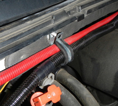
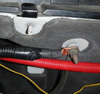
My dual battery writeup...

Disclaimer: Links on this page pointing to Amazon, eBay and other sites may include affiliate code. If you click them and make a purchase, we may earn a small commission.

OP
OP
Martinjmpr

Martinjmpr

Full Access Member
Joined
Jun 4, 2015
Posts
378
Reaction score
183
Location
Littleton, Co
What piece of equipment did you remove to get the plate in there?

:confused: Not sure what you mean by 'plate?' Are you talking about the battery tray?

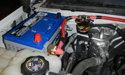
If you look on the firewall under the curved brace you should see a metal platform or bracket that goes from the inside of the passenger side fender to the firewall. The factory battery tray just replaces that bracket. It's a straight bolt on. The curved brace that sits on top of the fender also needs to come off as the battery will not fit underneath it.

You do need to unbolt the reservoir for the radiator when you are putting the battery tray in. You don't need to disconnect it, but you do need to unbolt it so you can move it out of the way. Installing the battery tray was super easy, actually probably the easiest part of this whole thing.
 
OP
OP
Martinjmpr

Martinjmpr

Full Access Member
Joined
Jun 4, 2015
Posts
378
Reaction score
183
Location
Littleton, Co
EDIT: REALIZED THE PICS WEREN'T SHOWING UP. SHOULD BE FIXED NOW.

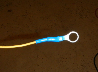
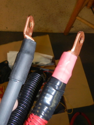
All right, I wanted to post this in case anyone was following. After I posted my pictures on Expedition Portal, a few of the people there pointed out to me that the way I had crimped on my cable ends was not correct. I basically just mashed them on with a bench vise. Well apparently that doesn't provide a very good connection and can lead to excess heat buildup and (worst case) a fire. Best case is that power going to and from the 2nd battery can be inconsistent.

Connecting the cable ends correctly requires either soldering them using a "slug" of solder and a tin cable lug, or using a copper cable lug and a special crimper that will squeeze all the wire in the cable together, "cold welding" it to the cable lug.

One of the Expedition Portal members, Dave, graciously volunteered to let me use his cable lug crimpers. Not only that, he had a full supply of lugs and some good quality shrink-tubing to seal the ends. So last Sunday morning, I drove over to his house and we correctly crimped all 3 cables.

I put it all back together last night. Here are the nice, neatly crimped cables that Dave made for me:
.
DB13_zpsu17brf0k.jpg
.
Sweet, right? elkgrin.gif
.
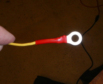
My experience with Dave using shrink tubing prompted me to go out and buy a heat gun and re-do my small cables, so instead of the "redneck mechanic" look of multiple wraps of black electrical tape, I have this:
.

db14_zps85i4uowe.jpg

db15_zpsb6zyfxi2.jpg

.
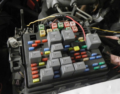
Once I got those made, I popped the cover off of the fuse box so I could route the power wire for the controller underneath it. It's easy to remove the cover to the box, but you do have to take off the crescent-shaped hood brace in order to get it out.
.
db16_zpsyrvaqhcy.jpg
.
Got everything hooked back up...
.
db17_zps5yybd1u0.jpg
.
Tested it and...it didn't work. Then, after frantically checking every circuit, I realized that I'd re-connected all the cables - except the one from the house battery to the truck ground! rolleyes.gif
.
Hooked that up and measured the voltage. Engine running, starter battery: 14.33v. House battery: 14.33v. wings.gif
.
Looking into the engine compartment there are the ends of two machine screws sticking out. I was thinking this would be a great place for my insulated clamps.
.
db19_zpst0eoxkp0.jpg
.
Only thing is, I don't know what nut size goes on here. Any ideas?
.
Should be the same as this screw on the driver's side above the ground strap:
.
db20_zpsprzu2fgp.jpg
.
I assume this is a metric size, but I don't know. Any ideas?
.
Anyway, next project will be getting power to the passenger compartment for the fridge, but I think I will post a new topic for that one. If anyone has any questions feel free to shoot me a PM or post up here.
.
And BTW I just want to point out that if I can do this project, as ignorant and fumble-fingered as I am, then pretty much anyone can do it.
 
Last edited:
OP
OP
Martinjmpr

Martinjmpr

Full Access Member
Joined
Jun 4, 2015
Posts
378
Reaction score
183
Location
Littleton, Co
Finished up the install this weekend with a 12v outlet on the rear driver's side

As usual, it turned out to be much more work than I thought it would.
.
There's a cautionary tale here, too, about making sure you have the right tools and not being so impatient to get something done that you rush through the process and break something.
.
With the dual battery system functioning it was now time to turn to the whole reason WHY I put the dual battery in in the first place: So I could have a dedicated power source to run the fridge (among other things, but the fridge was priority no. 1.) In order to do that, I had to get power from my 2nd battery to the interior compartment of the truck.
.
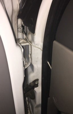
This turned out to be a major hassle. I tried to push a wire through one of the existing wire grommets but no luck. At this point I didn't want to run the risk of damaging a critical electrical circuit so I tried to figure out what to do next. The only thing I could think of was to run the wire underneath the fender to the door, then poked a hole and ran it right through the door weatherstripping and from there I could drop it into the channel underneath the sill plate.
.
db26_zpsnljr8mwh.jpg
.
Looking at that, I'm thinking it would be prudent to either put some wire loom over the wire or even some rubber tubing to protect the wire from damage (the door does NOT contact the wire - I checked - but I don't want to run the even the risk of a bare wire shorting it out (although it is fuse protected at the battery end.)
.

It's not a particularly elegant solution, but given the fact that I was running out of time it was all I could come up with. I wish there was an easier way to put a wire through the firewall - I have to say that of all the tasks I've had to do on a vehicle, figuring out how to do this seemingly simple one has proved to be the most difficult of them all.
.
In the old days it was easy but modern vehicles have so much CRAP underneath the dash that it's nearly impossible to get through the firewall in a manner that is safe and "elegant" without looking like a hack job (It would be nice if manufacturers just put a blank "accessory grommet" somewhere on the firewall for just such things. Oh well, a man can dream, right? rolleyes.gif )
.
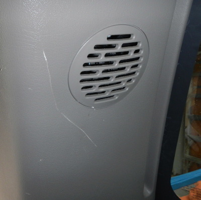
Anyway, I was able to get most of the interior trim panels out - as others have said, they are held in with clips that just pop out. The only problem I had was with the one on the interior of the D-pillar. Since my Suburban has speakers there, the D-pillar is somehow held on with the speaker. I ended up pulling it just a little to hard and this was the result:
.
db22_zpsb27rh7hh.jpg
.
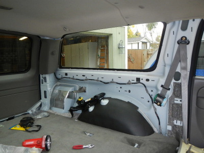
I couldn't see any way to remove a screw or anything so I still don't know how that panel is supposed to come off. Luckily for me, all the other panels came off without too much drama. The result was an interior that looked like this:
.
db23_zpsszeblsaj.jpg
.
My plan was to find a way on the fender-cover to put the dual 12v outlet. Finding a place that was both high enough that it would not be covered up by cargo, and also not on a curved portion of the panel, proved to be a little bit difficult but after looking around, I finally decided to mount the 12v outlets horizontally just behind the 3rd row seat cup holder.
.
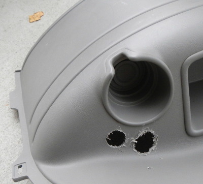
Unfortunately, this was another area where my impatience cost me: I needed to drill a couple of 1" holes for the 12v outlets. I didn't have any actual 1" hole saws but I did have a spade bit. Of course, spade bits work great for wood - for plastic, not so much. The first hole went OK because I took my time but I rushed the 2nd hole and the result was not pretty:
.
db24_zpsij7tbimm.jpg
.
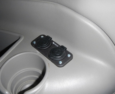
Yup, it punched out a section that was a good 1/4" bigger than it needed to be. I was able to smooth out the edges with a dremel tool and luckily for me, the cover plate for the outlet hides most of my mistake:
.
db25_zpsgjx9qb3t.jpg
.
For a ground I just ran a wire to the metal bracket that holds the fender cover up (the aluminum bracket you can see sticking out from the side of the body in the photo above.) I checked it with the volt meter and was getting a good solid 12.4v reading, so after that I hooked up the outlet and buttoned everything up.
.
Unfortunately while reassembling the plastic panels I broke off one of the smaller pins on the fender cover. Not a huge deal, but, once again, it shows the results of impatience (it was getting dark by this time and I just wanted to be DONE!)
.
You can see from the picture that there are two outlets - one is a conventional 12v power outlet and the other is a dual USB. The USB is not currently connected to anything but eventually I'll hook it up, probably by splitting the 12g wire that comes from the battery. I had thought about running another wire all the way from the battery but I don't think that's neccessary - USB has such a small power draw and it's not like we're going to connect that to anything other than a cell phone or iPod. If I had to do it over again I'd have just gone with the single 12v outlet. Easier to position and easier to fit in.
.
So, overall I have to say I learned a lot in doing this. And of course I have to thank all the folks here on the board who helped me out, especially Dave! I certainly could not have done it without you!
.
Even though this is "done" I will probably continue to "tweak" it but at least now I have a working system.
 

05Single

afraid of the dark
Joined
Feb 26, 2015
Posts
8,183
Reaction score
11,448
Wow what a write up , nice work on everything.:cheers:
 

moab

Full Access Member
Joined
Jan 7, 2017
Posts
157
Reaction score
28
How much was the isolator? And how did you decide to buy the one you bought? I'm also wondering how much this would be at a local RV shop if you supplied the battery and isolator?

GREAT write up. Thank you so much for all your time and effort on this. I'm going to have this done to my 07. Which is even easier as they came with the second battery tray already installed in the front driver side.
 
OP
OP
Martinjmpr

Martinjmpr

Full Access Member
Joined
Jun 4, 2015
Posts
378
Reaction score
183
Location
Littleton, Co
How much was the isolator? And how did you decide to buy the one you bought? I'm also wondering how much this would be at a local RV shop if you supplied the battery and isolator?

The isolator was about $43 on Amazon:

https://www.amazon.com/gp/product/B001HBYXVS/ref=oh_aui_detailpage_o09_s00?ie=UTF8&psc=1

As for why I chose that one, well, it may seem silly but I was essentially copying my setup from one I saw on http://www.expeditionportal.com, and so I figured I'd use the same isolator he did.

As far as what a shop might charge, that's hard to say. It would probably depend on how experienced they were doing things like this. I probably have a minimum of 10 - 12 hours of work into this project, but I'm working by myself with very little equipment and doing things very slowly (this is my first time doing something like that.) I would hope a shop could do it in maybe 2 hours of shop time which around here tends to run $90 - $100/hr.

GREAT write up. Thank you so much for all your time and effort on this. I'm going to have this done to my 07. Which is even easier as they came with the second battery tray already installed in the front driver side.

The tray was actually the easiest part. The harder parts were things like figuring out where to mount the isolator and how to attach it to the mounting point (as you can see, I decided to use jack nuts and screws but some people use sheet metal screws) , making the cables (which required a special tool I didn't have so I had to drive to someone's house and he helped me make them) and figuring out where to run the wire through the firewall. You'll also have to come up with a way to tap into the fuse box, I just lifted the fuse box cover off and ran a wire underneath it to an add-a-circuit fuse tap.

I'm still not happy about the way the power wire runs to the back of the truck and once it warms up a bit I plan on pushing that wire through a rubber grommet on the firewall, probably using a rifle cleaning rod to pull it through.
 
OP
OP
Martinjmpr

Martinjmpr

Full Access Member
Joined
Jun 4, 2015
Posts
378
Reaction score
183
Location
Littleton, Co
By the way I tested this system out on a trip to Arizona in November and it worked great. Even though we had electrical power at the campsite (if we have 120v AC electrical I always plug the fridge into the 120v line) it gave me great peace of mind to know that the fridge was running off of a separate battery from the starter battery.
 

JonnyTahoe

Full Access Member
Joined
Apr 14, 2011
Posts
1,249
Reaction score
771
Location
Minneapolis
What year is your truck, mine has a few factory studs coming out of the firewall that look different than yours. I will show pics later today.
 

Forum statistics

Threads
129,270
Posts
1,813,083
Members
92,379
Latest member
Pepper1700
Top