tast101
Supporting Member
From TF.Com
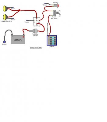
RenegadeTahoe said:After getting my windows tinted, I realized that it was EXTREMELY difficult to see out my back window at night (street isn't lit well... the lights reflect off the wall and make it hard to see). I looked for solutions, but couldn't find anything that really fit. I saw that you can just throw in a 55w light bulb in the stock location, but it didn't help much and was reported to burn / melt the plastic lens after time. There was a kit made by White Night that gave me an idea.... here's a picture:

They wanted $99 for the kit plus some extra wiring harnesses and adapter brackets to make it all work without extra wiring. I could not afford it, but I could pick up some driving lights and do it myself.
I started with Pilot HID-simulated driving lights (in other words: cheap fog lights... anything with 55w dual lights will do) for $19.99. Here's a picture:
...and a link
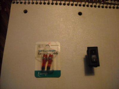
These lights came with the wiring, mounting hardware, and a switch(which I'm not going to use). You will need a few connectors:
Tap splice:
Disconnects: (optional... if you want to be able to disconnect the lights in the future)
OR... if you can just get this:
and use a male disconnect, it is much easier. Otherwise, you will have to create your own disconnect on the splice. Again, the disconnect is optional. you can simply use the tap splice to permanantly splice the wires, if that's what you prefer. I knew I wanted to wire in a switch at a later time and would need the disconnect, so I used it. For sake of this how-to, I will use the disconnect that I used.
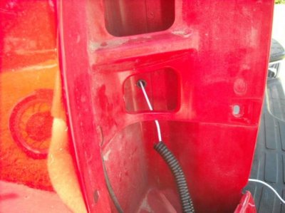
Once you have the parts, you will need to find the light green wire that comes out of the factory trailering harness. (should be the one to the middle pins of the harness). For safety sake, test the wire with a continuity tester or a multimeter to make sure you've got the right one. I turned the key to "on", put on the parking brake, and shifted to reverse to test this. ***USE EXTREME CAUTION - THE VEHCILE CAN ROLL OVER YOU IF YOU DO NOT USE THE PARKING BRAKE OR A WHEEL STOP***
After you test the wire to make sure you got the right one, place the open end of the tap splice onto the wire. Stick an un-stripped wire into the closed side (there is a barrier in the middle, so make sure your wire goes through on the right side, or you will not splice the wire correctly) When both wires are in, use pliars to crimp down the metal connector and secure the connector strap across the connector. Strip the other end of the wire you spliced into it and place a female disconnect onto it, and crimp it. This will give you a spliced disconnect. Tuck the new connection back into the wire loom and tape it up with electrical tape to make sure it's secure and safe from the elements. (leave the disconnect hanging out).
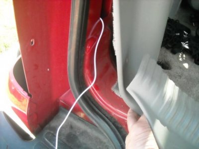
Now, it's time to find a ground. There are a few places to find a ground, but I was uncomfortable with using the grounding strap for the fuel filler neck, so I created my own. Using a self-tapping screw (or drill a hole, and use a fine-threaded sheet metal screw) you can attach a new ground to the chassis. I did mine on the driver's side, right behind the bumper / hitch mount. Attach the black wire on the light harness (from the Autozone kit) to your ground. The kit has a small open-end connector on it that can be easily attached to a ground.
At this point, you can add a male connector to the white wire in the cabling kit and plug it into the disconnect if you want, however I would wait until the lights are mounted before connecting power to them.
I chose a spot in the bumper (between two long holes) to mount my lights. I also wanted to aim them a little to the sides to get a better viewing angle. This is not required, however if you do, you will get a better angle. The supplied screws are not meant to mount to metal, so I would not recommend using them. Use a sheet metal screw (3/16 is a good size) that is fine or standard threaded (DO NOT USE COURSE THREADS AS IT WILL NOT SECURE CORRECTLY). Drill your pilot holes (if you're using 3/16 thread screws, I would use 5/32 pilot holes as the bumper is rather thick and WILL bind a screw if the hole is too tight. Mount the lights using the supplied brackets and bolts / lock washers and finger tighten. (I used the middle hole as it let me adjust the lights better) Connect the supplied wiring from the lights to the correct color-matched connectors. If you have not added your male end to the white wire, do so now and plug it into your connector. Test the lights by using the method stated above for turning on your reverse lights. The lights should come on with your reverse lights. If they do not, check fuses, and make sure you have all wires secured and matched up correctly. If they turn on, you're done. You can either tuck the wires up into the bumper and secure them to the wirelooms that go across the back, or if you're like me and wanted the "stock" look, you can buy 10 feet of 3/8" wire loom for about $.99 at a hardware store (read: Home Depot) and make it clean. I zip-tied all the extra wiring together and placed it into the loom, then zip-tied the loom out of the way.
When you're done, your Tahoe should look like this:
And the people seeing you back up will see this:
For a mere $25-30, you can have as bright of lights as the $99+ systems, and it doesn't require relocating the trailer wiring harness.
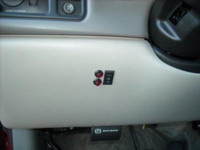
If you're good with electrical, you can also wire in a 3-way switch that will allow you to turn them off, turn them on by reverse, and turn them on for utility. That will be my next step.