You are using an out of date browser. It may not display this or other websites correctly.
You should upgrade or use an alternative browser.
You should upgrade or use an alternative browser.
Np 246 pinout?
- Thread starter xDan
- Start date
Disclaimer: Links on this page pointing to Amazon, eBay and other sites may include affiliate code. If you click them and make a purchase, we may earn a small commission.
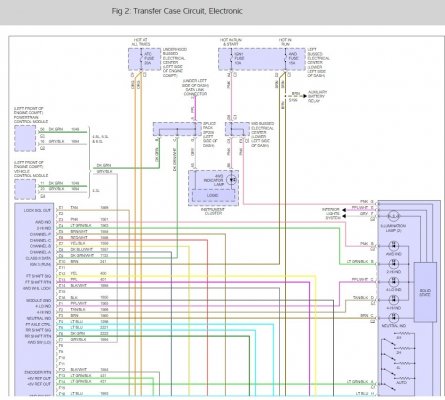
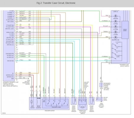
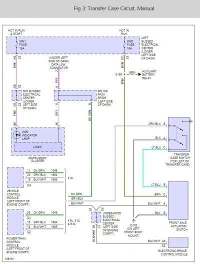
That shows the 8v system to the dash (select) switch. Mine is 5v reference from the ATCM (TCCM) on F14 (and F13 to the encoder motor). Seems to be for the earlier models; not sure how much different the newer systems would be.
Last edited:
xDan
Member
- Joined
- Nov 3, 2017
- Posts
- 89
- Reaction score
- 40
Yea. The 2003-2006 is unique, but mostly similar to the previous iteration, in functionality. NBS is 5V ref. and has motor A/B simplified control vs the older system. I'm ordering an encoder motor assembly...if that fixes it, I may tear down my old one to maybe figure out the differences.That shows the 8v system to the dash (select) switch. Mine is 5v reference from the ATCM (TCCM) on F14 (and F13 to the encoder motor). Seems to be for the earlier models; not sure how much different the newer systems would be.
Yea. The 2003-2006 is unique, but mostly similar to the previous iteration, in functionality. NBS is 5V ref. and has motor A/B simplified control vs the older system. I'm ordering an encoder motor assembly...if that fixes it, I may tear down my old one to maybe figure out the differences.
Have you had your encoder motor off? If so, does the shift shaft on the T/C have two flats, or is it splined?
xDan
Member
- Joined
- Nov 3, 2017
- Posts
- 89
- Reaction score
- 40
I found a good writeup on the avalanche forums, the motor lock circuit, when de-energized (disabled in tech 2) actually LOCKS the encoder motor in it's current gear selection. When showing ENABLED in the tech 2, that energizes the circuit and the lock is turned OFF. Only during gear change commands and in auto 4wd (during an adaptive mode) is the lock circuit enabled (turning OFF the lock)...so it should only enable when actively changing the clutch fork on the clutch, like you said. It is counterintuitive. This is a DC motor electronic lock within the encoder motor control circuitry, not anywhere else, only commanded by the TCCM.It's curious, though, that the Auto setting is commanding the front diff actuator. I'm not sure that it should do that until the TCCM tells it to engage, and for that you need wheel speed differences. But I'm not sure, and I'll have to check into that next time I have the Tech 2 plugged in to mine. One thing you could do is remove the front diff actuator and see if it's engaging during both (actual, per the Tech 2) Auto and 4x4 modes. In Auto it absolutely shouldn't engage until the TCCM senses speed differences between the front and rear wheels.
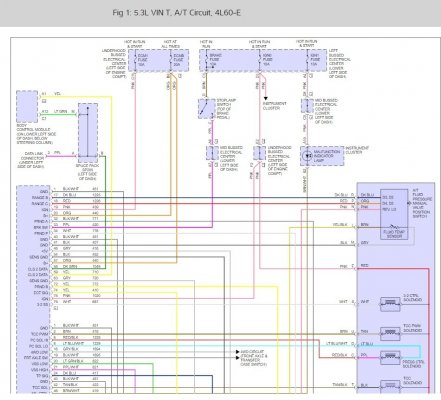
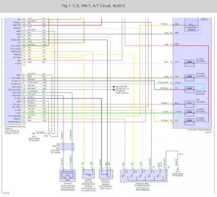
I never found a service manual for 2003-2006 that showed a different wiring diagram.
Then also this S/B-
GM SERVICE BULLETIN
Bulletin No.: 05-04-21-003C
Date: April 15, 2008
Subject:
Service 4WD Light Illuminated, DTC C0374 Set (Inspect Wiring Harness to Transfer Case Speed Sensors,, Replace Wiring Harness) Models:
2004-2007 Buick Rainier
2003-2006 Chevrolet Avalanche, Suburban, Tahoe
2003-2007 Chevrolet Silverado Classic, TrailBlazer, TrailBlazer EXT
2003-2006 GMC Yukon, Yukon XL
2003-2007 GMC Envoy, Envoy XL, Sierra Classic
2003-2004 Oldsmobile Bravada
2005-2007 Saab 9-7X With Four Wheel Drive or All-Wheel Drive
and Active All-Wheel Drive (RPO NP4) or Active Two-Speed (RPO NP8) Transfer Case
Supercede:
This bulletin is being revised to update the Model and Warranty Information. Please discard Corporate Bulletin Number 05-04-21-003B (Section 04 - Driveline/Axle).
CONDITION:
Some customers may comment on intermittent illumination of the Service 4WD light. Upon investigation, the technician may find DTC C0374 set. The customer may also comment on intermittent erratic operation of the 4WD or AWD system after driving through rain/snow or simply going through a car wash.
CAUSE:
The speed sensor signal may have become corrupted. Possible openings in the speed sensor wire insulation (twisted pairs) can allow water intrusion. Also wire connections contaminated by water may result in short circuits and erroneous speed sensor readings. This most often occurs on the rear speed sensor circuit.
CORRECTION:
Inspect the wiring harness to the transfer case speed sensors. On Rainier, TrailBlazer, Envoy and 9-7X models, fabricate a replacement speed sensor harness between the C101 connector and the speed sensors. Completely inspect and test all wiring. Refer to Speed Signal Front Axle Actuator and Indicators schematic in SI.
Replace the affected twisted pairs. Do not over-twist the two wires in the replacement harness. Wires should be twisted at a rate of 9 revolutions per foot. Use service connector pack, P/N 88987993 at the speed sensor end and terminal, P/N 15326267, at C101.
Terminal testing tools and service terminals can be found in Terminal Repair Kit J 38125. Terminals are available from SPX/Kent-Moore.
The smaller transfer case harness splices into the larger chassis harness a few inches in front of the cross-member. The chassis harness routes along the left side of the frame under the driver door area. Use nylon tie straps to secure the fabricated harness to the main chassis harness between the transfer case and C101.
On the full-size pickup and full-size utility models, replace the 2.2 m (88 in) pigtail harness that runs from the C151 connector under the hood to the transfer case. Use either harness P/N 15832722 or 15224663 depending on vehicle equipment. Refer to Propshaft Speed Sensors Front Axle Actuator and Transfer Case Shift Control Switch schematic in SI.
Important: Technicians should verify the integrity of the splice joints after the repair. All splice joints and connections should seal properly against water or a repeat condition can occur.
I actually knew that about the encoder motor. Kind of works reverse of what you'd think, until it's explained.
I was talking about the actuator on the front diff -- it's commanded on in 4HI and 4LO, engaging the front diff fulltime. But it should be commanded off in AUTO, until the TCCM's speed sensors' input tells it to engage. That's the AUTO part of the mode, engaging/disengaging only the front diff.
I was talking about the actuator on the front diff -- it's commanded on in 4HI and 4LO, engaging the front diff fulltime. But it should be commanded off in AUTO, until the TCCM's speed sensors' input tells it to engage. That's the AUTO part of the mode, engaging/disengaging only the front diff.
xDan
Member
- Joined
- Nov 3, 2017
- Posts
- 89
- Reaction score
- 40
Interesting. I think I'm going to go over the disconnected harness, including output shaft and front speed sensor harnesses.I never found a service manual for 2003-2006 that showed a different wiring diagram.
Then also this S/B-
GM SERVICE BULLETIN
Bulletin No.: 05-04-21-003C
Date: April 15, 2008
Subject:
Service 4WD Light Illuminated, DTC C0374 Set (Inspect Wiring Harness to Transfer Case Speed Sensors,, Replace Wiring Harness) Models:
2004-2007 Buick Rainier
2003-2006 Chevrolet Avalanche, Suburban, Tahoe
2003-2007 Chevrolet Silverado Classic, TrailBlazer, TrailBlazer EXT
2003-2006 GMC Yukon, Yukon XL
2003-2007 GMC Envoy, Envoy XL, Sierra Classic
2003-2004 Oldsmobile Bravada
2005-2007 Saab 9-7X With Four Wheel Drive or All-Wheel Drive
and Active All-Wheel Drive (RPO NP4) or Active Two-Speed (RPO NP8) Transfer Case
Supercede:
This bulletin is being revised to update the Model and Warranty Information. Please discard Corporate Bulletin Number 05-04-21-003B (Section 04 - Driveline/Axle).
CONDITION:
Some customers may comment on intermittent illumination of the Service 4WD light. Upon investigation, the technician may find DTC C0374 set. The customer may also comment on intermittent erratic operation of the 4WD or AWD system after driving through rain/snow or simply going through a car wash.
CAUSE:
The speed sensor signal may have become corrupted. Possible openings in the speed sensor wire insulation (twisted pairs) can allow water intrusion. Also wire connections contaminated by water may result in short circuits and erroneous speed sensor readings. This most often occurs on the rear speed sensor circuit.
CORRECTION:
Inspect the wiring harness to the transfer case speed sensors. On Rainier, TrailBlazer, Envoy and 9-7X models, fabricate a replacement speed sensor harness between the C101 connector and the speed sensors. Completely inspect and test all wiring. Refer to Speed Signal Front Axle Actuator and Indicators schematic in SI.
Replace the affected twisted pairs. Do not over-twist the two wires in the replacement harness. Wires should be twisted at a rate of 9 revolutions per foot. Use service connector pack, P/N 88987993 at the speed sensor end and terminal, P/N 15326267, at C101.
Terminal testing tools and service terminals can be found in Terminal Repair Kit J 38125. Terminals are available from SPX/Kent-Moore.
The smaller transfer case harness splices into the larger chassis harness a few inches in front of the cross-member. The chassis harness routes along the left side of the frame under the driver door area. Use nylon tie straps to secure the fabricated harness to the main chassis harness between the transfer case and C101.
On the full-size pickup and full-size utility models, replace the 2.2 m (88 in) pigtail harness that runs from the C151 connector under the hood to the transfer case. Use either harness P/N 15832722 or 15224663 depending on vehicle equipment. Refer to Propshaft Speed Sensors Front Axle Actuator and Transfer Case Shift Control Switch schematic in SI.
Important: Technicians should verify the integrity of the splice joints after the repair. All splice joints and connections should seal properly against water or a repeat condition can occur.
Oh ok, gotcha. Have you tested the speed sensors before, or changed them? I'm waiting on a new encoder motor to get here and my garage is full...and the weather is bad so I'm not rushing to take it out just yet. I am going to tear down the old encoder though and have a look. With that removed I should be able to manually shift the transfer case.I actually knew that about the encoder motor. Kind of works reverse of what you'd think, until it's explained.
I was talking about the actuator on the front diff -- it's commanded on in 4HI and 4LO, engaging the front diff fulltime. But it should be commanded off in AUTO, until the TCCM's speed sensors' input tells it to engage. That's the AUTO part of the mode, engaging/disengaging only the front diff.
Oh ok, gotcha. Have you tested the speed sensors before, or changed them? I'm waiting on a new encoder motor to get here and my garage is full...and the weather is bad so I'm not rushing to take it out just yet. I am going to tear down the old encoder though and have a look. With that removed I should be able to manually shift the transfer case.
I never had to inspect the speed sensor harness, since the encoder motor was the solution for me. If you have have a Tech 2 you may be able to view the T/C speed sensors' activity, if it comes to that. What I need to do is to get someone to chauffeur me around while I play with the Tech 2, to see what live data interests me. Too crazy doing it while driving.
When you shift the transfer case, it may help to have the driveshafts "free" by being in neutral and/or having it on four jackstands or a lift. We had to wiggle the rear shaft a bit to get mine to easily shift the T/C with the splined shaft.
xDan
Member
- Joined
- Nov 3, 2017
- Posts
- 89
- Reaction score
- 40
Oh yea I saw the speed sensor data, all zeros.
Similar threads
- Replies
- 67
- Views
- 26K
- Replies
- 7
- Views
- 3K

