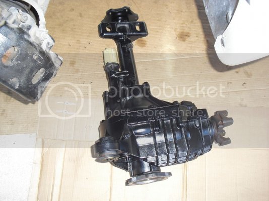
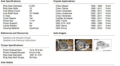
Front differential rebuild GM 8.25 IFS (needs to be a sticky)

Disclaimer: Links on this page pointing to Amazon, eBay and other sites may include affiliate code. If you click them and make a purchase, we may earn a small commission.

ivin74

05 NBS Nali
Joined
Aug 3, 2014
Posts
2,271
Reaction score
2,325
Location
Htown, Texas
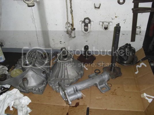
While searching how to rebuild the front diff on my Yukon I ran into this thread that I think should be a stick on this site. Its a very detail DIY, the only thing that I would add to this DIY is to replace the side gear washers and the spider gear washers on the carrier since you are already there.

I copied and paste this DIY from the other site so don't give me any credit for this write up.

http://www.truckmodcentral.com/forums/f168/rebuilding-gm-8-25-ifs-differential-**56k-beware-pic-heavy**-13813/

Rebuilding A GM 8.25 IFS Differential **56K Beware! Pic Heavy**
I am going to try to cover the basics on rebuilding the front differential in a GM truck with the 8.25" IFS differential. I am doing a gear change but also a full rebuild while I have it apart.

Parts you'll need: Ring & Pinion Gear set, Master Install Kit, lock tabs (2)- (GM PN - 15588312)

Make sure to download the pdf attachment at the bottom of this post, it contains all torque specs you'll need and a few notes that I have found while doing this myself.

Tools needed: General hand tools, bearing pullers, slide hammer, shop press, dial indicator with magnetic base, inch pound bar type torque wrench, special spanner wrench: http://www.yukongear.com/ProductDeta...px?ProdID=5227

To start off place your diff over a 5 gallon bucket and drain the gear oil from it.
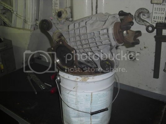
Frontdiffteardown001.jpg

Now place the diff up on a work bench, or the floor if it won't fit on your bench. Stand the diff up with the short shaft down and remove the bolts around the case.
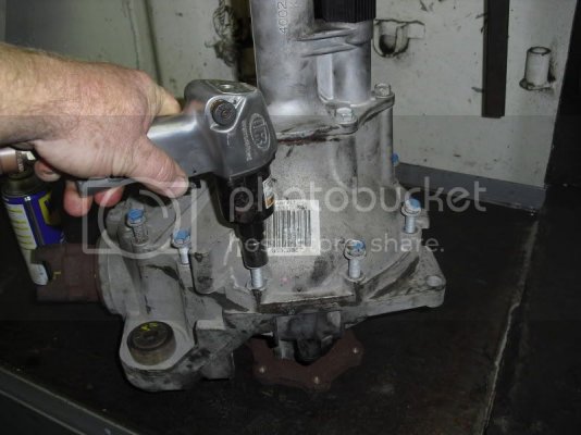
Frontdiffteardown002.jpg

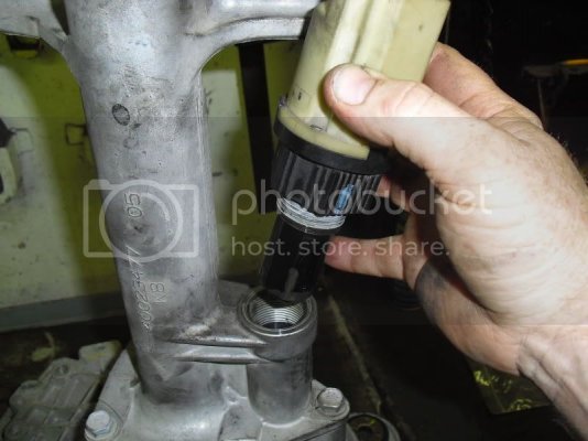
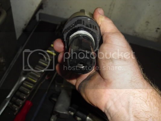
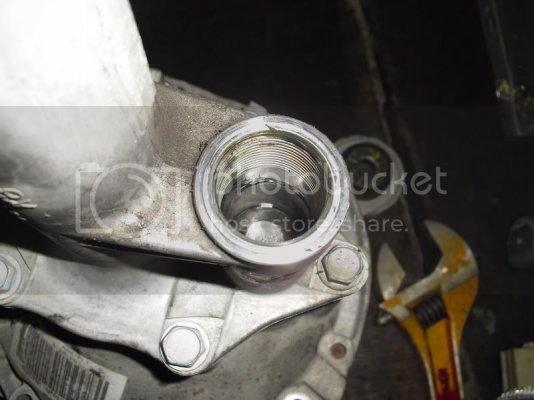
Remove the electric motor actuator by unscrewing then set aside.
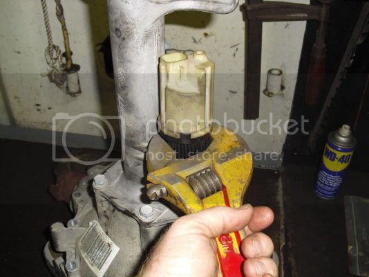
Frontdiffteardown003.jpg

Frontdiffteardown004.jpg

Frontdiffteardown005.jpg

Frontdiffteardown006.jpg

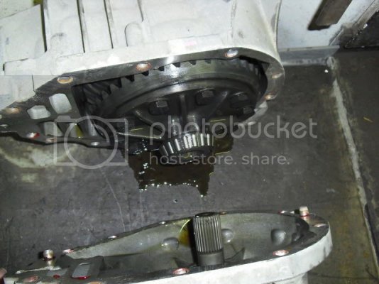
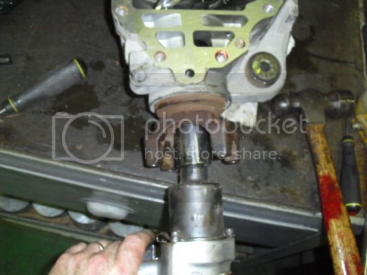
Now lay the diff over on it's side and place a slide hammer on the axle flange. Give it a few good wraps and the casing should split apart.
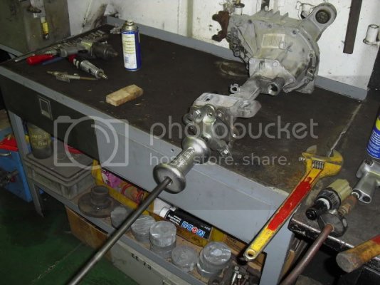
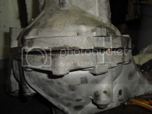
Frontdiffteardown008.jpg

Frontdiffteardown007.jpg

Frontdiffteardown009.jpg

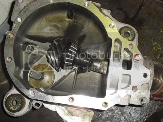
With the case split in two, flip the section over with the short shaft pointing up. Lift the case up and the carrier may fall out. If not, which was my case, use your slide hammer on the axle flange and give it a few tugs up. This should lift the case free of the carrier.
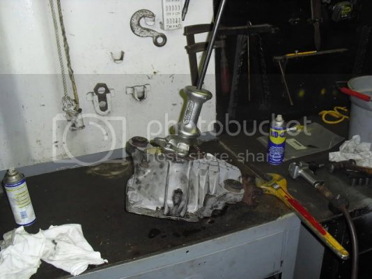
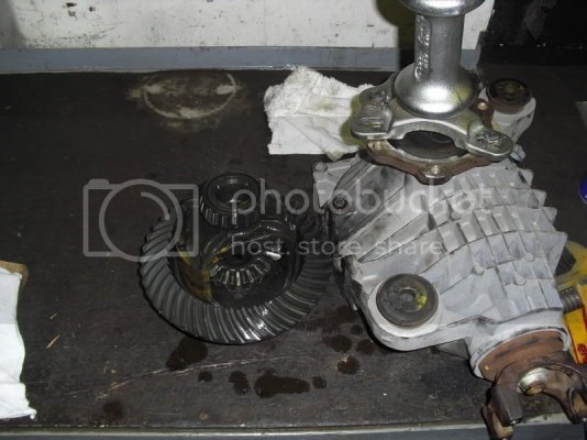
Frontdiffteardown010.jpg

Frontdiffteardown011.jpg

Flip the case over and using the handle of a ball pein hammer tap the stub axle out of the housing.
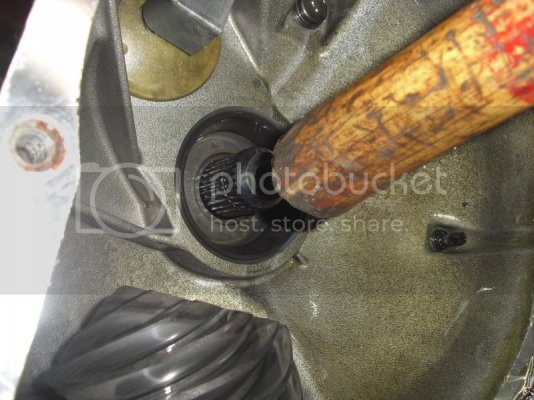
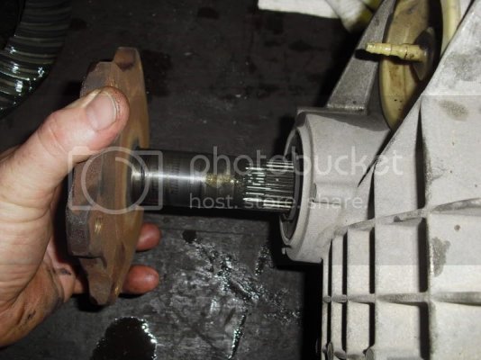
Frontdiffteardown012.jpg

Frontdiffteardown013.jpg

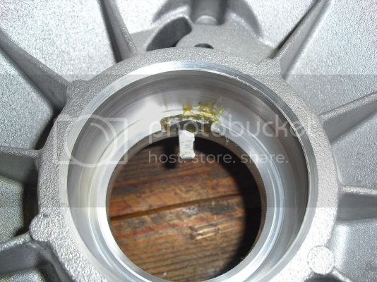
The stub axle was held into the carrier by a small circlip, look down in the spline area of the carrier and you should see it in a groove.
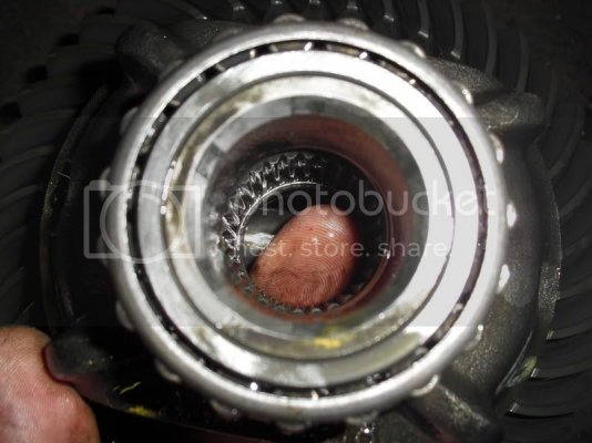
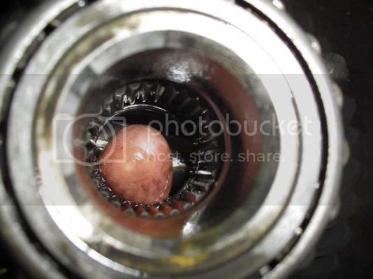
Frontdiffteardown014.jpg

Frontdiffteardown015.jpg

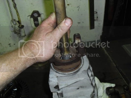
Using a long punch knock the stub axle seal out.
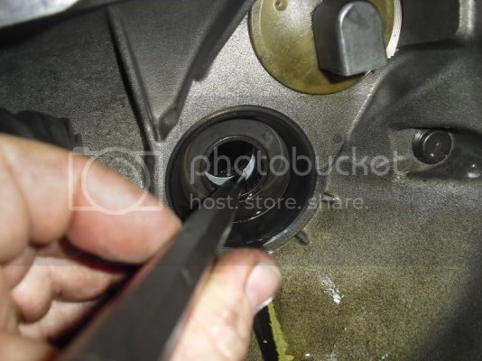
Frontdiffteardown016.jpg

Frontdiffteardown017.jpg

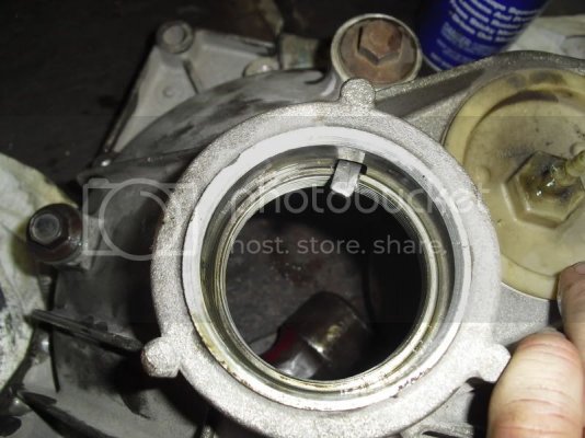
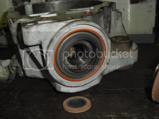
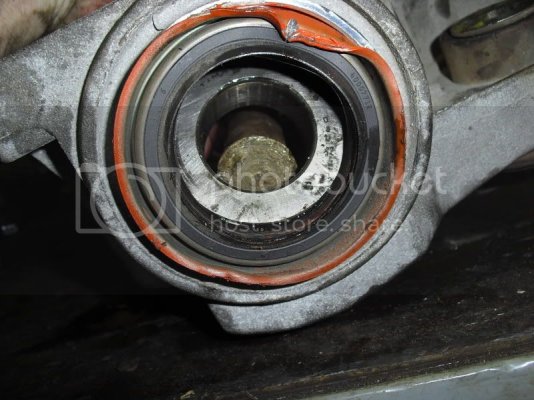
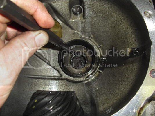
This will give you access to the stub axle bearing, lock tab, adjuster and carrier bearing. Using a screwdriver or chisel pry the lock tab up enough to be free.
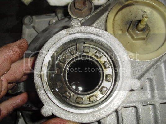
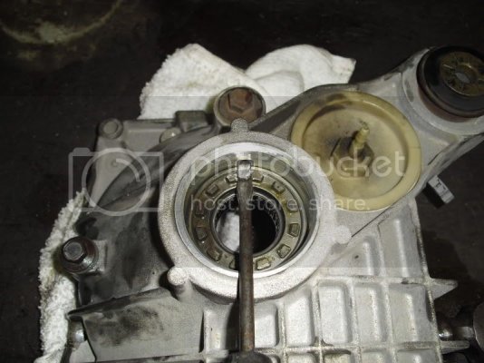
Frontdiffteardown018.jpg

Frontdiffteardown019.jpg

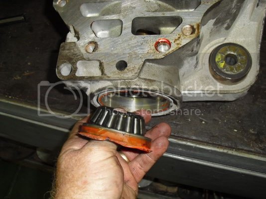
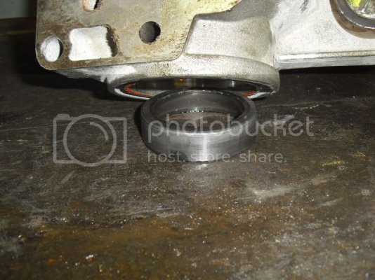
Flip the case over and drive out the axle bearing with a punch.
Frontdiffteardown020.jpg
 
Last edited:
OP
OP
ivin74

ivin74

05 NBS Nali
Joined
Aug 3, 2014
Posts
2,271
Reaction score
2,325
Location
Htown, Texas
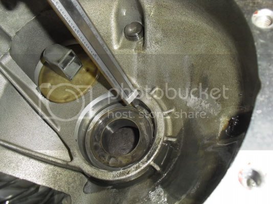
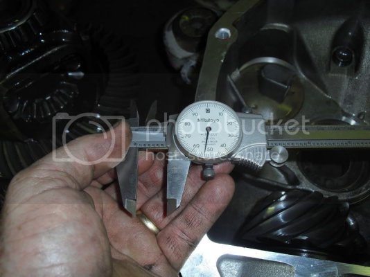
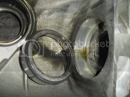
Now this is where my experience ( or lack of it) will help you. The adjusters should be driven out, towards the inside of the case. Using a brass drift hammer them out evenly. This will also allow you to replace the lock tabs. If the carrier bearing races have fallen out before you drive out the adjusters, take a measurement and write it down. This will help for setup down the road.

Frontdiffteardown021.jpg

Frontdiffteardown023.jpg


How not to do it, but it won't hurt to do it this way. Just a few unnecessary steps is all.

Frontdiffteardown024.jpg

Frontdiffteardown025.jpg

**I should have left the two pieces screwed together before driving them out. Learn from my mistakes**

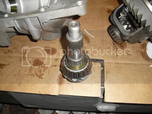
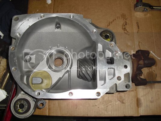
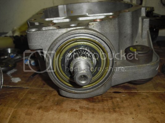
Remove the pinion nut and drive the pinion out. Leave the nut screwed on a few threads until the yoke turns loose of the splines, then remove the nut and yoke. Finish driving the pinion out.

Frontdiffteardown026.jpg

Frontdiffteardown027.jpg

Frontdiffteardown028.jpg

Remove the pinion seal and outer bearing. For ease of removal, using a chisel fold over a portion of the lip of the seal. Then stick a pry bar in and roll the seal out, catching the bearing as the seal comes out.

Frontdiffteardown029.jpg

Frontdiffteardown030.jpg

Frontdiffteardown031.jpg

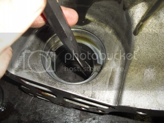
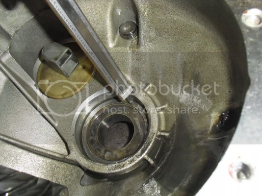
Using a long punch from the outside, drive the inner pinion bearing race out.

Frontdiffteardown034.jpg

Flip the case over and drive out the outer pinion bearing race.

Frontdiffteardown035.jpg

Frontdiffteardown036.jpg

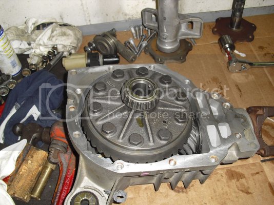
Remove the old ring gear from the carrier and remember these are left handed bolts.

Frontdiffteardown037.jpg

Frontdiffteardown039.jpg

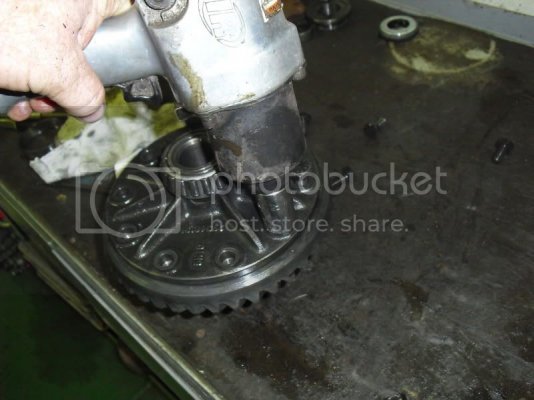
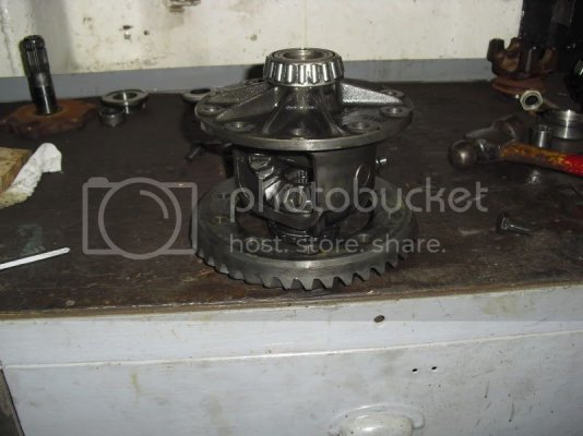
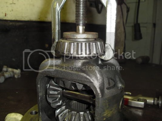
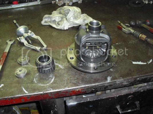
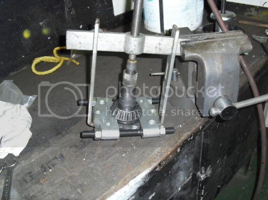
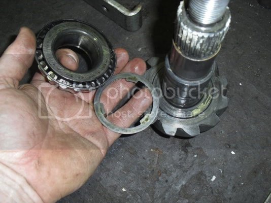
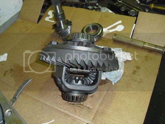
Using a gear puller remove the carrier bearings. I also suggest changing out the washers inside the side gears and the spider gears since you have made it this far.

Frontdiffteardown040.jpg

Frontdiffteardown041.jpg

I pulled the inner pinion bearing off to measure the factory shim, this gave me a starting point for the new gear set.

Frontdiffteardown042.jpg

Frontdiffteardown043.jpg
 
Last edited:
OP
OP
ivin74

ivin74

05 NBS Nali
Joined
Aug 3, 2014
Posts
2,271
Reaction score
2,325
Location
Htown, Texas
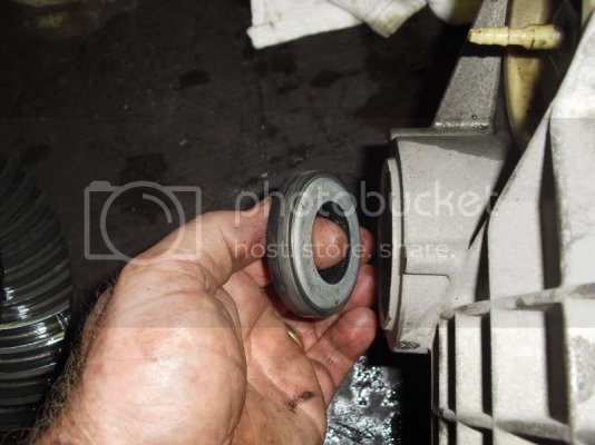
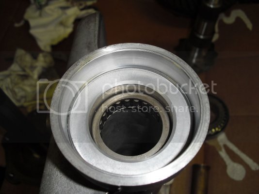
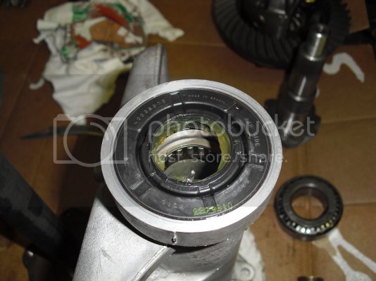
So now with all of the parts clean let's start re-assembling the differential. Take the long shaft housing and install the axle bearing and axle seal. Smear a little bearing grease on the lip of the seal after it's installed.

Frontdiff2002.jpg

Frontdiff2003.jpg

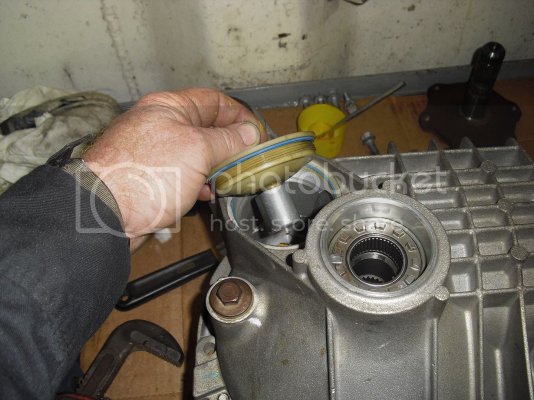
Insert the axle shaft into the housing and flip it over, resting on the axle flange.

Frontdiff2004.jpg

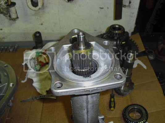
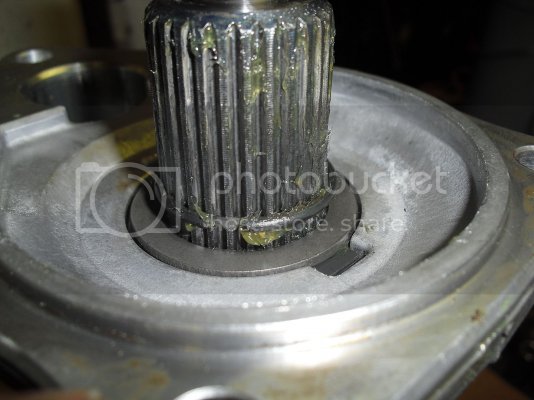
Place your tabbed locating washer, thrust washer and circlip onto the axle. Make sure the circlip is properly seated in the groove of the axle splines.

Frontdiff2005.jpg

Frontdiff2006.jpg

Prep your carrier by installing the ring gear and carrier bearings. Ring gear and bearings will probably need to be pressed on using a shop press or a block of wood and a hammer. Use Lock tite on the ring gear bolts and tighten to spec.

Frontdiff2007.jpg

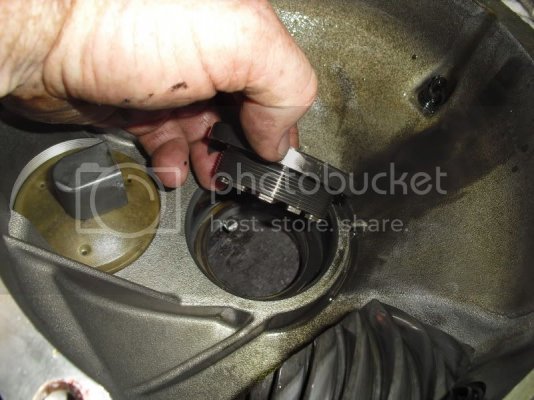
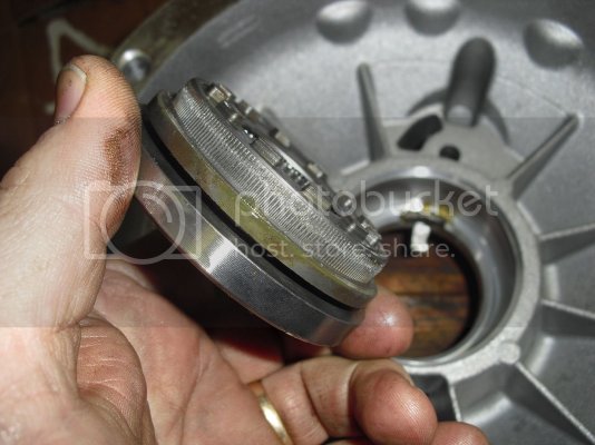
Take your carrier bearing adjusters and install the roller bearings in both. Install new lock tabs, using a dab of grease to hold them in place, then drive the adjusters into place in both case halves. Set your distance on the adjusters back to about what they where when you removed them, this will just give you a starting point for setup.

Frontdiff2026.jpg

Frontdiff2027.jpg


Frontdiffteardown021.jpg


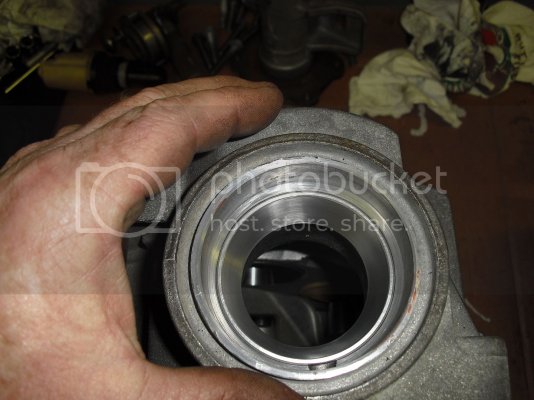
Install both carrier bearing races, also called cups, into the cases.

Frontdiff2008.jpg

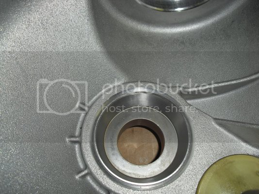
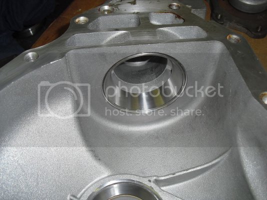
Install the inner and outer pinion bearing cups.

Frontdiff2009.jpg

Frontdiff2012.jpg
 
OP
OP
ivin74

ivin74

05 NBS Nali
Joined
Aug 3, 2014
Posts
2,271
Reaction score
2,325
Location
Htown, Texas
If you are doing the front on your own you probably did the rear on your own. Using the inner pinion setup bearing, from your rear diff install/setup, and the factory thickness of shims on the pinion. Put the pinion into the case without a crush sleeve. Using the old outer pinion bearing, with the ID ground out for setup, install the bearing and yoke, washer and old pinion nut. Tighten up snug until you get about one revolution of spin out of the yoke when spun by hand.

Frontdiff2013.jpg

Frontdiff2015.jpg


Place the assembled carrier into the case and snug up the bolts drawing the two halves together. Do not get too carried away tightening and put anything in a bind. If you need to loosen the adjusters as the case comes together do so.

Frontdiff2016.jpg

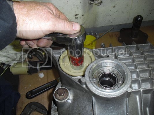
Once your case is together, remove the large plastic plug on the side of the case. This will give you access to the ring gear for setup checking.

Frontdiff2018.jpg

Frontdiff2019.jpg

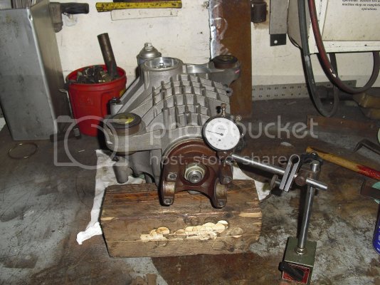
Setting back lash is a little different with the front diff. Place the diff on a good solid workbench, with a dial indicator reading the yoke. Yes I said reading from the yoke.

This takes some getting used to the feel to get right. Check back lash by taking the yoke reading and dividing by 2, this will give you the proper backlash. It's best to either have a buddy weigh the diff down or place a heavy dumb bell on the case to keep unnecessary movement from skewing your backlash reading. Like I said this takes some time to get the hang of.

Frontdiff2025.jpg

Make backlash adjustment at the adjuster, using the special spanner. I didn't have the special spanner and will not do another front diff without one again. It was a major PITA without it and I managed to rip a finger nail almost completely off when my home made tool slipped.
sad.gif
Get the tool.

If your backlash is too large: move the carrier closer to the pinion with the adjusters.
If your backlash is too close: move the carrier away from the pinion with the adjusters.

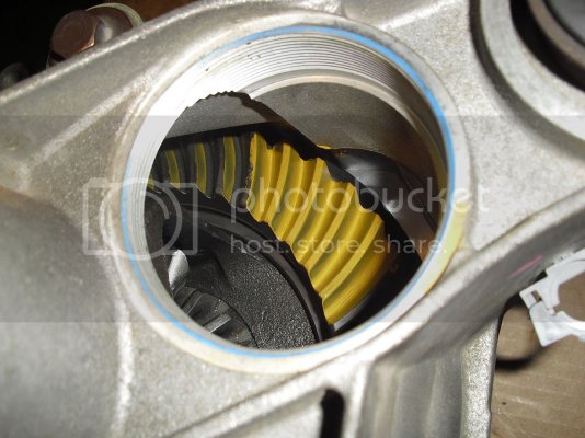
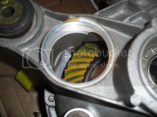
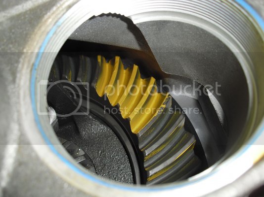
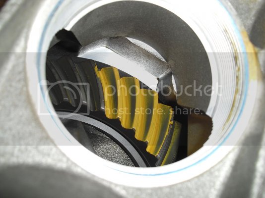
Once backlash is set it's time to run the mesh pattern. Paint gear marking paste on about 4~5 teeth, front and back.

Frontdiff2024.jpg

Rotate the marked teeth through several cycles, forward and reverse then check your pattern. Adjust pinion depth to attain the proper pattern. This can take some serious time getting the correct pattern. I had the case apart about 7 or 8 times in this process, so be patient.
cheers.gif


A helpful tip that I read AFTER I did this, was to use a 1/2 drill motor to spin the yoke. The guy used an extension that was ground down to fit the drill chuck along with a socket on the yoke nut. Then spin the hell out of the pinion, stop and check your pattern. It sure would have been helpful if I had seen that before doing this one.


Frontdiff2023.jpg

Frontdiff2022.jpg

Frontdiff2021.jpg
 
OP
OP
ivin74

ivin74

05 NBS Nali
Joined
Aug 3, 2014
Posts
2,271
Reaction score
2,325
Location
Htown, Texas
Now we'll assume you have achieved the proper mesh pattern and backlash is set. It's time to take it all apart one last time. Remove the carrier and clean off the gear paste. Remove the pinon and setup bearings.

Install the new inner pinion bearing into the case and install the pinion seal. Install the new inner pinion bearing by pressing it on with a shop press. Slip the crush sleeve onto the pinion and insert it into the housing.

Frontdiff2028.jpg

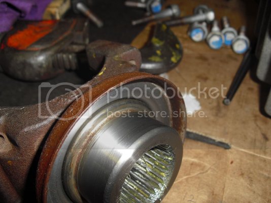
Clean the seal surface of the yoke and install it over the splines of the pinion. Install the washer and nut and draw the yoke onto the pinion, being careful to not over tighten. Just tight enough to seat the bearings in the races and still be able to spin freely.

Frontdiff2029.jpg

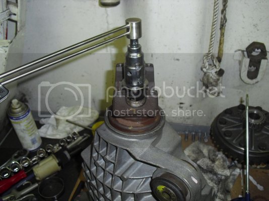
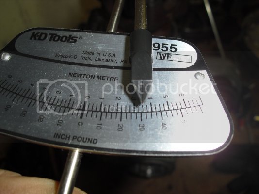
Once the yoke is snugged up begin checking pinion bearing pre-load using an inch pound bar type torque wrench. Keep reading below for more detail instructions

Frontdiff2031.jpg

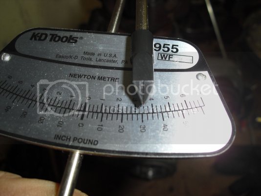
Set pinion bearing preload to spec.

Frontdiff2030.jpg

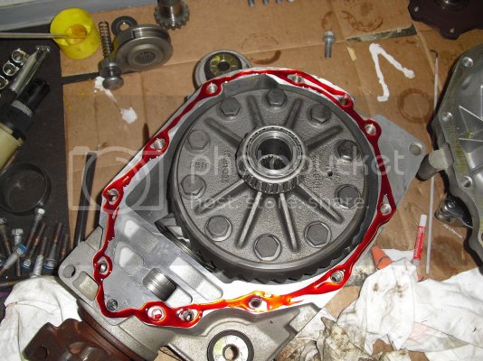
Install carrier and use some sealer on case sealing surfaces. Put case halves together and torque bolts to spec.

Frontdiff2032.jpg

Place diff back on a bench and double check backlash. To adjust carrier bearing preload, use the torque wrench on the yoke nut and tighten up the adjuster that is farthest away from the ring gear until proper preload is achieved. Check backlash one last time, if satisfactory using a punch knock over the adjuster lock tabs into place.

Frontdiff2030.jpg

Put all remaining items back as removed. The stub shaft will require a slap with a mallet to get it seated. Double check engagement of the circlip by pulling the shaft out, if it comes out by hand the circlip didn't seat.

Put the long axle housing along with shift fork, gears and spring back together using some sealer on the mating surfaces. Use a little pipe dope on the electric shift motor threads and a little grease on the oring of the large plastic plug. Paint the diff if you want and re-install.

Frontdiff2033.jpg
 
Last edited:
OP
OP
ivin74

ivin74

05 NBS Nali
Joined
Aug 3, 2014
Posts
2,271
Reaction score
2,325
Location
Htown, Texas
To set the pinion preload see below

DO NOT USE AN IMPACT TO COMPRESS THE NEW CRUSH SLEEVE. DOING THAT TO A NEW CRUSH SLEEVE WILL RUIN IT.


Here are the steps you should follow:


1) As best you can, make a mark on your pinion flange, and make a corresponding mark on the case itself and the nut. Make sure they are aligned. Also mark the driveshaft yoke to the pinion flange. Assembling all this back the EXACT way it came off will prevent you from having to re-clock the driveshaft to prevent vibrations.


2) Get ahold of an INCH-POUND torque wrench with a dial gauge (Oreilly’s has them for $30 bucks). DO NOT USE A "CLICK" STYLE TORQUE WRENCH, IT WON'T WORK. You need one that looks like this:


http://www.sears.com/kd-tools-beam-...SellerId=Sears&prdNo=2&blockNo=2&blockType=G2


3) Use some adapters, and match that inch-lb torque wrench up to a socket that fits over the pinion nut. I think it's 21mm if my memory serves me.


4) Using that wrench, check your axle's preload (GM 8.25 IFS New is 14 to 19 In lb). Put the wrench on, and slowly apply force while watching the needle. You should reach a point where the gears start to turn. Write the max torque number down, it should be in the range of 14-19 in-lbs. Repeat this process about 3-4 more times with the pinion flange in different positions and check it in the reverse direction. You're doing this to get the best average number they should be very close no matter the position of the flange.


5) Realign the marks you made earlier and count the number of threads that are showing past the pinion nut. Remember this number as well.


6) Using a GOOD 3-jaw pulley puller, remove the pinion flange. Make sure to grease the tip when you seat it in the end of the pinion gear. Be sure not to rotate the assembly when removing the flange.


7) With your pinion flange in-hand, you should take to the task of cleaning out any crap in the splines on it and the pinion gear. The less crap, the easier it will go back on.


8) Clean the front surface of the sealing face, and about an 1/8" inward on the inner surface. Scotch-brite works great. So does some fine sandpaper. Keep any debris out of your axle's internals. No need to go all human-power sander on it. A light cleaning will do just fine.


9) Apply a very thin amount of RTV around the inner lip of your new seal (this will give you extra security from leaks). A little goes a long way. I'm talking like no more than 1/8" of RTV all the way around. You do want it to dry some time this century.


10) Set the new seal in the casing and using a rubber hammer or a nice plastic dead blow, tap the outer face evenly to seat the seal. You're going to have to hit it with some force, but don't wail on it. If you bend it, you're going to have to pick up another one. Make sure it's seated flush all the way around.


11) Allow some time for the RTV to dry. Usually about an hour or so. Grab a beer or some lunch.


12) After the RTV has had some time to dry, get your pinion flange back out and fit it on the end of your pinion shaft. It will fit TIGHT. Just get it started as best you can. Make sure to align your marks from earlier.


13) Using the old pinion nut (they are reusable) and a large wrench (breaker bar), SLOWLY (DO NOT USE AN IMPACT) turn the nut to force the flange onto the shaft. It's gonna move around a bit, as the flange is what holds the pinion gear straight, but don't sweat it. This is gonna be a PITA. I had to use a large extension braced against the flange bolts that I threaded back in to keep it from spinning. It may not go in perfectly straight because of the torque you're applying, but it's fine, as it gets closer to the final position, it will straighten out.


14) As you turn this nut down, be careful. It's gonna take a fair amount of force. Using the number of threads you counted earlier, turn the nut until you're within two of those threads. After you hit those two, SLOW WAY DOWN with your turning. If it feels like the nut is getting harder to turn, stop immediately.


15) This is where your preload measurement comes into play. What you need to do now is turn the nut a little bit, and then check the preload with the inch-lb torque wrench. Do this repeatedly until you reach your original number. You should have the nut very close to the original orientation, however, the preload amount is the MOST important part. Getting it to what it was when you started prevents excessive bearing wear and keeps your gears where they were originally set. It's okay to go just a bit over, but don't let it go over more than 5 in-lbs.


The reason the preload measurement is so important is the crush sleeve. The crush sleeve is cylindrical bushing that sits just in front of the thrust bearing of the pinion gear. When doing a gear install, you put a new crush sleeve in, and tighten the pinion nut to 250 ft-lbs. This extreme torque deforms the crush sleeve. However, due to the elasticity of the steel, the crush sleeve expands just a bit after you've torqued it. This deformation produces a force that sets the correct load for the thrust bearing. This is called preload and is what you measured earlier. Crush too much, you get excessive bearing wear. Crush too little, you have excessive play.


Crush sleeves are supposed to be 1 time use, HOWEVER, if you retorque to the exact same specs, you will be fine. If you go over the original number, then you have re-deformed the crush sleeve and there's no telling what kind of actual preload you have.
 
Last edited:
OP
OP
ivin74

ivin74

05 NBS Nali
Joined
Aug 3, 2014
Posts
2,271
Reaction score
2,325
Location
Htown, Texas
To remove the spider gear/ side gear washers please see the video showned below. To re install do the opposite. thx


Forum statistics

Threads
129,213
Posts
1,812,262
Members
92,313
Latest member
kylesimmons
Top