wikipedia-
A simple electromagnetic relay consists of a coil of wire wrapped around a soft iron core, an iron yoke which provides a low reluctance path for magnetic flux, a movable iron armature, and one or more sets of contacts (there are two in the relay pictured). The armature is hinged to the yoke and mechanically linked to one or more sets of moving contacts. It is held in place by a spring so that when the relay is de-energized there is an air gap in the magnetic circuit. In this condition, one of the two sets of contacts in the relay pictured is closed, and the other set is open. Other relays may have more or fewer sets of contacts depending on their function. The relay in the picture also has a wire connecting the armature to the yoke. This ensures continuity of the circuit between the moving contacts on the armature, and the circuit track on the printed circuit board (PCB) via the yoke, which is soldered to the PCB.
When an electric current is passed through the coil it generates a magnetic field that activates the armature, and the consequent movement of the movable contact(s) either makes or breaks (depending upon construction) a connection with a fixed contact. If the set of contacts was closed when the relay was de-energized, then the movement opens the contacts and breaks the connection, and vice versa if the contacts were open. When the current to the coil is switched off, the armature is returned by a force, approximately half as strong as the magnetic force, to its relaxed position. Usually this force is provided by a spring, but gravity is also used commonly in industrial motor starters. Most relays are manufactured to operate quickly. In a low-voltage application this reduces noise; in a high voltage or current application it reduces arcing.
When the coil is energized with direct current, a diode is often placed across the coil to dissipate the energy from the collapsing magnetic field at deactivation, which would otherwise generate a voltage spike dangerous to semiconductor circuit components. Some automotive relays include a diode inside the relay case. Alternatively, a contact protection network consisting of a capacitor and resistor in series (snubber circuit) may absorb the surge. If the coil is designed to be energized with alternating current (AC), a small copper "shading ring" can be crimped to the end of the solenoid, creating a small out-of-phase current which increases the minimum pull on the armature during the AC cycle.[1]
A solid-state relay uses a thyristor or other solid-state switching device, activated by the control signal, to switch the controlled load, instead of a solenoid. An optocoupler (a light-emitting diode (LED) coupled with a photo transistor) can be used to isolate control and controlled circuits.


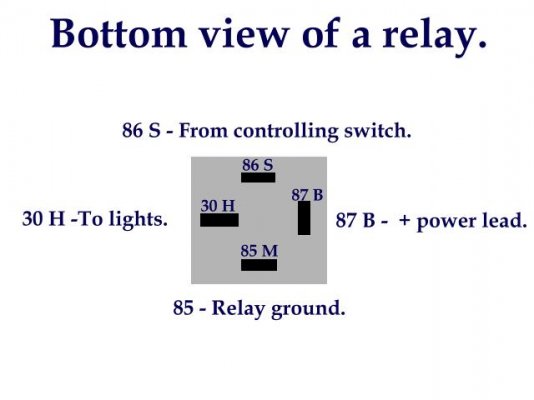
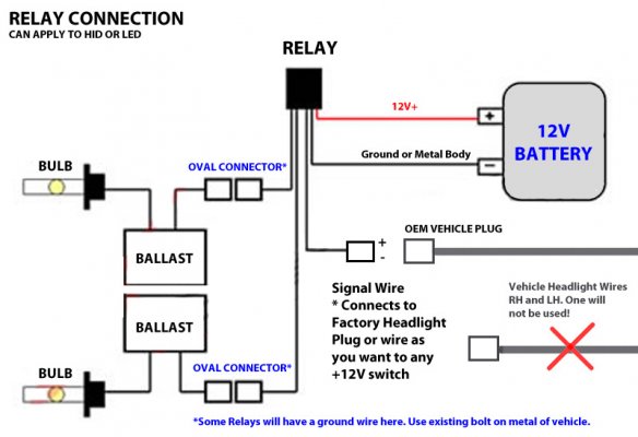
There are many other types of electrical relays but I figured the one above would be most common for auto use. And if you are using a relay for lights, you can find them pre wired with fuses.


