Edit: I talked to nrod_tx privately and he shared some more information, and linked me to his post on
the12volt.com. His installer added some extension wires that don't all match the wire colors of the Whelen light. I've updated this post to better reflect the current situation.
It was making a fast clicking noise because he wired it wrong, based on what I see in the vehicle's
electrical wiring diagrams. Hopefully the BCM wasn't damaged. That "OFF DOOR ON" switch only grounds one of two pins from the BCM, depending on the position it is in. It is not a negative "door open" signal. Here is the info on the wires that he tapped into:
Connector X316 Headliner Harness to Overhead Console Harness:
| 6 | GY/BU | Courtesy Lamp Switch Signal | Circuit 156 |
| 10 | YE | LED Backlight Dimming Control | Circuit 6817 |
| 17 | RD/YE | Battery Positive Voltage | Circuit 240 |
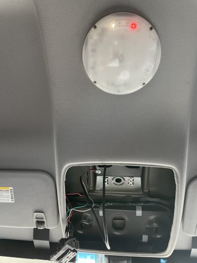
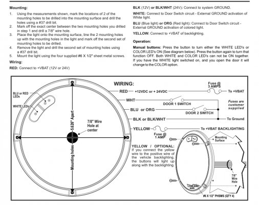
It looks like you have the Whelen 60CREGCS, from which I see:
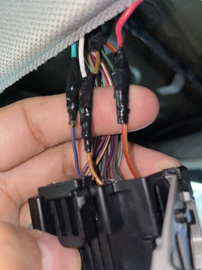
| Whelen Wire | Extension Wire | Present Use | Status |
| Red | Red | Connected to "Battery Positive" | Good |
| Black | Black | Connected to self-tapped ground | Good enough |
| Yellow | White | Connected to "LED Backlight Dimming Control" | Good |
| White | Teal | Connected to "Courtesy Lamp Switch Signal" | Wrong |
I don't see the yellow wire from the Whelen light anywhere, but you didn't mention it, so I'm not worried about it. Also, per the Whelen docs, that blue wire should be orange. Maybe they ran out of orange or made a change. *shrug*
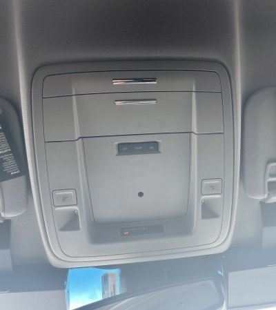
Rather than tap into the five different door trigger wires near the BCM (and diode isolate them), it will probably be easier to tap into the positive signal for the existing lighting. This is especially true if you want the Whelen light to mimic the behavior of the other lights. The door trigger is only one of several different methods of activating the dome lights.
The first issue is that the Whelen door trigger wire is expecting a negative signal, but the "Courtesy Lamp Switch Signal" is positive. The polarity of that signal needs to be reversed. A standard relay can do that that as seen in the below image.
Note that a flyback/snubber diode should be installed on the relay to protect the BCM.

I haven't had the opportunity to verify (using a multimeter/oscilloscope), but I believe the "Courtesy Lamp Switch Signal" wire uses PWM (pulse width modulation) to control the factory dome lights. This is possibly going to be the second issue. Assuming the PWM signal ranges between 0 and ~12 Volts, you should be able to use a passive RC low pass filter to smooth out the pulses and provide a steady voltage to keep the relay from bouncing open and closed (contact chatter). Time for another image!

On the left, you have the "Courtesy Lamp Switch Signal," then an inline resistor. After that, you have a capacitor that is grounded, and the filtered signal that goes to the load. In this case, the load would be the relay in the previous image.
So, here's what I would do in your situation:
1. Prepare the relay by soldering a diode across pins 85 and 86. The end with the white band should be towards pin 86
2. Cut the teal wire, leaving enough to work with on each side of the cut
3. Attach the teal wire that comes from the vehicle wiring harness to pin 86 on the relay
4. Attach the teal wire that comes from the Whelen light to pin 87 on the relay
5. Connect pins 30 and 85 to ground (using another ring terminal at that self-tapping screw)
Test it out by opening the doors, using the key fob to lock/unlock the doors, etc. If it works, you're done. But, if it doesn't...
1. Disconnect the teal wire from pin 86
2. Connect the resistor between the teal wire and pin 86
3. Put the capacitor between pin 86 (long lead) and ground (short lead)
Keep in mind this will be in a vehicle that is subject to constant vibration. Make sure all connections are mechanically strong before you close everything up.