You are using an out of date browser. It may not display this or other websites correctly.
You should upgrade or use an alternative browser.
You should upgrade or use an alternative browser.
6-HI Mod 2002
- Thread starter IcePhreak
- Start date
Disclaimer: Links on this page pointing to Amazon, eBay and other sites may include affiliate code. If you click them and make a purchase, we may earn a small commission.
ks03
Fool Excess Member
- Joined
- May 3, 2019
- Posts
- 307
- Reaction score
- 297
“Nothing is impossible...”
― Mahatma Gandhi
― Mahatma Gandhi
ks03
Fool Excess Member
- Joined
- May 3, 2019
- Posts
- 307
- Reaction score
- 297
have you read through....
https://www.tahoeyukonforum.com/threads/how-to-99-02-hi-6-with-diagram.24147/
https://www.tahoeyukonforum.com/threads/how-to-99-02-hi-6-with-diagram.24147/
SnowDrifter
Full Access Member
- Joined
- Sep 5, 2016
- Posts
- 2,405
- Reaction score
- 2,591
Awww pics are boinked in the write-up
Someone quote me so I can find this later. Will amend it when I'm able to make it out to the truck
Someone quote me so I can find this later. Will amend it when I'm able to make it out to the truck
Awww pics are boinked in the write-up
Someone quote me so I can find this later. Will amend it when I'm able to make it out to the truck
Duly quoted.
SnowDrifter
Full Access Member
- Joined
- Sep 5, 2016
- Posts
- 2,405
- Reaction score
- 2,591
ThankiesDuly quoted.
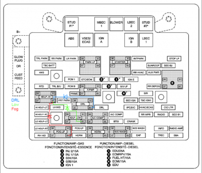
So these rigs are wired with a reverse switched ground. What that means, is that the switched power going to the relays is always "on," but the relay is triggered by switching the ground. As far as the reverse bit, it means pins 85 and 86 are switched. So contrary to a 'normal' relay, these ground through pin 85, and take switching supply through pin 86. The reason for that is it makes the fuse box a bit simpler internally, and allows the 12v supply to be bridged across pins 86 and 30 by a single piece of brass, which would also act as a dual purpose fuse.
If that's confusing, don't worry about it. Just refer to the diagram at the end of this comment.

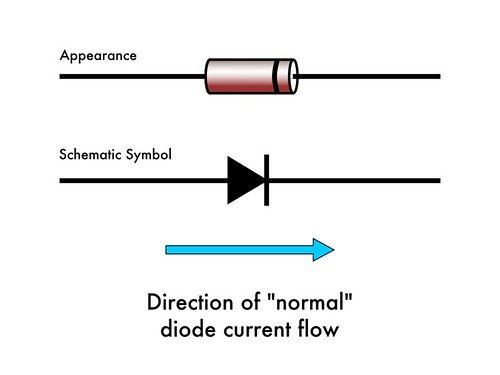
Now imagine, if you will, a diode is a one way valve for electricity. There's a signified of direction on there that'll be in the form of a colored ring closer to one side of the diode.

So what you need to do, is wire this in a manner, that when your high beams are triggered by grounding out that relay, the high beams / fog lights are also triggered. You can take advantage of the valviness of a diode to isolate the systems, such that they all function independently until the HBs are on, at which point current is allowed to flow in that direction.
Personally I have an 8-hi mod on mine. High, low, fogs, and running lights. I wanted ever last lumen I can get out of it.
Diagram is below.
As far as considerations: Organize everything such that the wires from the diode are insulated and / or not in contact with anything else. Switching current for 12v automotive relays is ~50-60 milliamps, or 0.050-0.060 amps. Size appropriately. Larger won't hurt you, but the leads on smaller units are generally easier to manage and will allow you to 'tuck' them into the socket without resorting to any wire splicing or tap-shims.
The other bit you'll want to consider is the reverse current breakdown of the diode. These rigs will max out at about 15.5v charging. So sizing to 18v or higher will give you plenty of safety factor.
tl;dr 18v or higher rated diode, 100ma+
Here's the wiring diagram for how I did mine. Just run pins 85 from whatever you want, to pin 85 on the high beam, with the ring on the diode closest to the high beam relay
Apologies if you're color blind. Should still be able to figure it out

Similar threads
- Replies
- 3
- Views
- 645
- Replies
- 13
- Views
- 267
- Replies
- 8
- Views
- 846
