2002 Tahoe efans

Disclaimer: Links on this page pointing to Amazon, eBay and other sites may include affiliate code. If you click them and make a purchase, we may earn a small commission.

V30Crewcab

Member
Joined
Apr 23, 2017
Posts
62
Reaction score
27
need more info on your coolant switch install. are you screwing the fitting into the motor, or teeing into the hose? that switch has to be grounded to work properly is why I'm asking.
 
OP
OP
C

Chris2144

Full Access Member
Joined
Jul 13, 2019
Posts
123
Reaction score
59
I am teeing into the hose and yes you are correct the switch must be grounded correctly I forgot to add that in the how to. There are multiple ideal locations to ground to right there. Or you can run another wire in with the loom and ground back by the relays. I choose the latter as I think it makes for a cleaner install.
 

lowpost99

Lowpost99
Joined
Apr 10, 2016
Posts
168
Reaction score
102
Location
Atlanta, GA
this is the positive. Note you can splice into this by pulling the fuse block apart Make up two 8 inch 10 gauge wires with eyelets and female blade connectors. Bolt these to one of the studs. Now connect them to 5 pin automotive relays. I know your wondering at this point huh where what. I will post pics of the relay and wiring diagram later on in the post
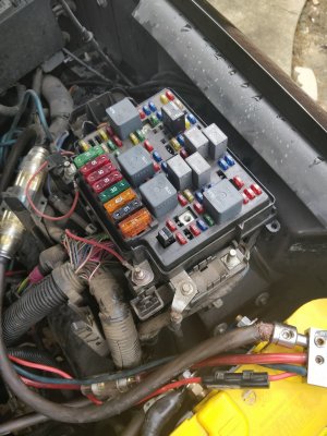
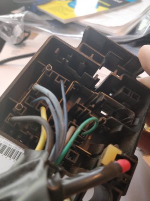
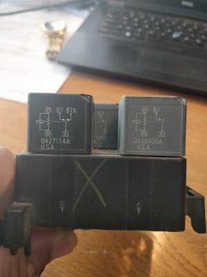
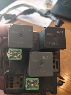
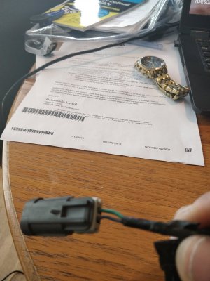
Chris, where is the green AC positive wire found around the fuse box? What are your thoughts about re purposing the OEM relays at the end of the harness. It uses 3 4 pin relays instead of 2 five pin ones. View attachment 227509 I think the relay block at the end of the OEM harness is built to power both relays by way of single power connection to the fusebox. Here is shot of some electrical diagram that may make sense to someone right away, but I need a primer. I think these relays are in some kind of series, and the small blue wires are speed control from the PCM.View attachment 227510 I don't think I need the two 8 in pieces above. I see 4 post under the fuse block. Two are red,one is black, and the last has nothing on it. I'm assuming either red one is fine for power and the black one is for ground. what is the last one? Here are pics of what I have:IMG_20190723_121135.jpg IMG_20190723_122535.jpg In the block, the green wire is likely the AC positive, and I bet the two smaller blue ones are joined into the plug pic below. This plug doesn't exist in my 00' so I'm guessing this is PCM related. I wonder if the green one is for the AC positive? Because looking at the bottom of the box, above it looks as if on set of fan wires black and yellow are organized slightly different, and that green wire is closer to one than the other. IMG_20190723_122608.jpg
 
Last edited:
OP
OP
C

Chris2144

Full Access Member
Joined
Jul 13, 2019
Posts
123
Reaction score
59
The relays in the OEM harness utilize the pcm negative command instead of the way I do it which utilizes the positive clutch command that goes to the ac clutch. I have not done that much as for looking into wiring up the OEM set however it does not look hard from just a brief look it appears you would eliminate one of the relays. When I get some time I'll try to look at it and figure out which wires go where and see if I can make a wiring diagram for it. I can't view yours but I have my own downloaded so if there the same then it would work
Note there is a relay for the ac and Iirc that green wire from the clutch goes to it. You have to pull the block out and splice in I just choose to splice in down by the compressor and tuck it in to the original loom. Either way will work though
 
Last edited:
OP
OP
C

Chris2144

Full Access Member
Joined
Jul 13, 2019
Posts
123
Reaction score
59
I would like to find one in a yard that hasn't been mangled and get a look at everything. For older trucks 04 and under I believe the plugs for the pcm change and is updated to utilize output from the pcm for the fans. Ours can be tuned for it but a pin and wire has to be added but I forget which one it is
 
OP
OP
C

Chris2144

Full Access Member
Joined
Jul 13, 2019
Posts
123
Reaction score
59
To answer on the studs. Yes the three are positive one comes from the battery. That 4th one I believe would be positive too. I think I remember seeing something saying it is used for glow plugs in diesel applications.


I make two pieces and wire up each relay seperate however you don't have to do it that way you can wire them from the same piece I just choose not to.
 

lowpost99

Lowpost99
Joined
Apr 10, 2016
Posts
168
Reaction score
102
Location
Atlanta, GA
Here are shots of the relays and the electrical diagrams on them. So where is my +AC clutch wire near the fuse box that I can tap into? Also I'm confused about the thermo switch. It needs to be grounded with a wire through the eyelet after you screw it in, but where/how does it get temp signal info to the relays? Doesn't it need another wire running to one of the relays?IMG_20190723_132132.jpg IMG_20190723_132125.jpg
 
OP
OP
C

Chris2144

Full Access Member
Joined
Jul 13, 2019
Posts
123
Reaction score
59
No the thermo switch is grounded. The idea of running in the head would eliminate the need to run a wire back to a ground as I have done before. The relay for temp is commanded by ground from the thermoswitch. Again in my install I ran the second wire back to the same ground as relay for the ac. When the temp reaches a preset point the switch closes and activates the relay which turns on the fan. For the ac wire in the fuse block I do not have a pic at the moment but there is a relay for it and iirc the wire color is the same coming out of that relay going to the ac clutch. Pulling the top off and locating the relay for it would identify which one it is then pull the fuse block splice into it and you have your ac command.

Note the relays are activated in different ways one is active through + being ac command and the other is activated through ground using the thermoswitch. That's my bad I forgot to clarify in the how to. Sorry it's my first one.

Now if you're trying to integrate that new 05+ harness then it will change the wiring from what I have described. My how to is not using that relay block or harness and is not controlled by the pcm for 04 and under
 

mattt

Full Access Member
Joined
Mar 27, 2014
Posts
735
Reaction score
304
Here are shots of the relays and the electrical diagrams on them. So where is my +AC clutch wire near the fuse box that I can tap into? Also I'm confused about the thermo switch. It needs to be grounded with a wire through the eyelet after you screw it in, but where/how does it get temp signal info to the relays? Doesn't it need another wire running to one of the relays?View attachment 227511 View attachment 227512

Is that the 05+ electric fan harness with relay block? If you know, how does that come out of the main harness and where is the relay block located? When I've looked previously, it appears the harness leaves the fan shroud and dives into a main wire harness. Thanks in advance.
 

Forum statistics

Threads
129,118
Posts
1,810,747
Members
92,206
Latest member
ckylec
Top