HOW-TO: 03-06 NBS Gauge cluster LED conversion

Disclaimer: Links on this page pointing to Amazon, eBay and other sites may include affiliate code. If you click them and make a purchase, we may earn a small commission.

OP
OP
S

ScottyBoy

Full Access Member
Joined
Jun 27, 2010
Posts
2,568
Reaction score
1,732
Location
Shreveport, La
@Kellyh, I do gave some USED but working stock cluster and AC panel bulbs. But I don't know for sure what type of AC panel they came from. The digital panels and the Manual AC panels (the one with the two temperature sliders) each use different bulbs.
The Manual panel has the bulbs wired in series, so I think they are 6 or 7 volt bulbs. While the digital panel has each bulb wired individually, and they are actually 12-14v bulbs like the cluster is.
 

Smoke Em All

Full Access Member
Joined
Jun 14, 2014
Posts
355
Reaction score
165
Location
Taylor,Texas
Anyone have a link for some good led strips? The LED bulbs in my 05 are all starting to burn out. Gonna try strips this go round.


Sent from my iPhone using Tapatalk
 

Smoke Em All

Full Access Member
Joined
Jun 14, 2014
Posts
355
Reaction score
165
Location
Taylor,Texas

dhulsey779

Full Access Member
Joined
Apr 3, 2014
Posts
181
Reaction score
114
Location
Phila
The LED's are white, but the gauge backing film has a blue tint to it. Got the gauge face for like $70-80


Sent from my iPhone using Tapatalk
 

mattt

Full Access Member
Joined
Mar 27, 2014
Posts
735
Reaction score
304
Anyone here in Socal that can swap cluster parts and overlay? I want to keep my existing cluster so I retain all existing info in the DIC. However, I also picked up a cluster from a Suburban 2500 which has the trans temp gauge. I'd like to have the trans temp gauge functional on my existing cluster with the overlay and the addition of a gauge motor. I have no interest in sending my 2 clusters out across the country to the popularly referred places here, which is why I'm looking local. Thanks in advance.
 

gonole

TYF Newbie
Joined
Dec 18, 2016
Posts
1
Reaction score
0
LEDs are becoming all the rage now, and more and more people are wanting to convert their interior lighting and gauge backlighting to LEDs. Here is some info on how to do this upgrade on any Tahoe, Yukon, Suburban, or Escalade from 2003-2006. Patience, a steady hand and soldering skills are a must if you want to tackle this upgrade. You will need about 10 5mm LEDs and enough resistors to go with them. The resistor value depends on whaich type and/or color LED you end up using. For the Blue LEDs I use, I pair them with 470 ohm resistors.


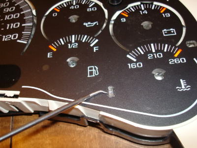
First, remove the cluster from the vehicle, and lay it out on your table or workbench. You will need a small flathead screwdriver or similar prying tool and pry the cluster open. You will want to take off the clear guage lense first. Do this by prying up the tabs, and slowly working your way around the cluster.
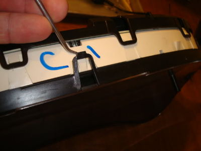
DSC02535.jpg

With the front lense/bezel removed, the cluster now looks this.
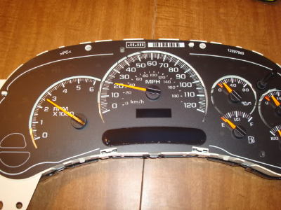
DSC02536.jpg

Next you will need to remove the guage needles. Be VERY careful with this step. You will need to mark where each needle is pointing, and re-install each needle in the same exact position when you re-assemble the cluster. To remove the needles, the best tool is a simple dinner fork. Yes, I said dinner fork. Slide the firk under each needle and pull straight up, being VERY CAREFUL to pop the needle off without turning it. Remember, you need to have it pointing in the same spot when done.
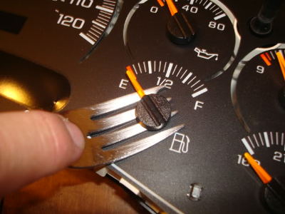
DSC02537.jpg

Now with all the needles removed, you can then remove the guage overlay. It is just popped onto some tabs or "nubs" around the cluster face. Just carefully pop the overlay up off of each nub.
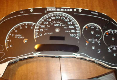
DSC02538.jpg
DSC02539.jpg

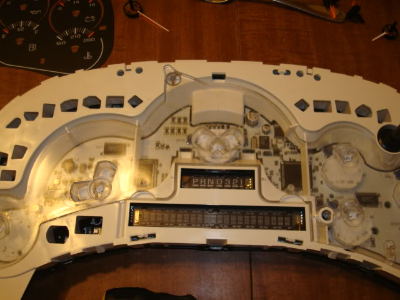
Now you have to lift out the clear light diffuser that is laying inside the cluster. Just carefull lift it straight up, it isnt secured to anything.
DSC02540.jpg

Now with the light diffuser removed.
DSC02541.jpg

Now you need to remove the white surround to get to the actual circuit board. You will need to pry it off just like the lense/bezel was.
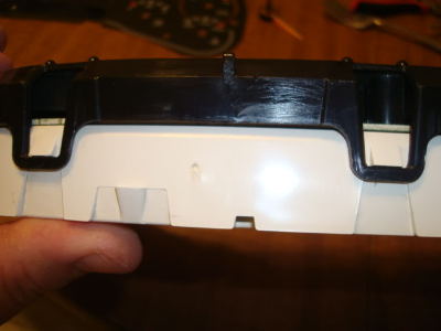
DSC02542.jpg

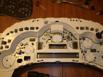
Now this is what you have with everything removed except the back of the cluster.
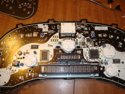
DSC02543.jpg

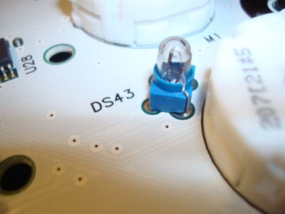
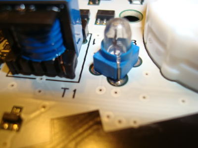
Now you need to remove all the stock bulbs from the board by unsoldering them. Only remove the ones on the white area of the board, which is the area behind the guages. This is what the stock bulbs look like.
DSC02544.jpg
DSC02545.jpg

At this point, you need to go plug the cluster back into your truck and use a meter to find out which solder terminals for each bulb are positive and negative. You do NOT want to use a conventional grounding test light, use a digital multimeter. You could also do this before you remove the bulbs if you choose to. Use a sharpie and mark each one postive and negative.
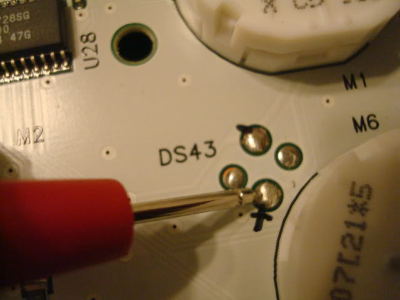
DSC02548.jpg

Another option is to go cut a harness pigtail from a truck in the junkyard and you can then power the cluster on your workbench with a 12v power supply. That is what I did.
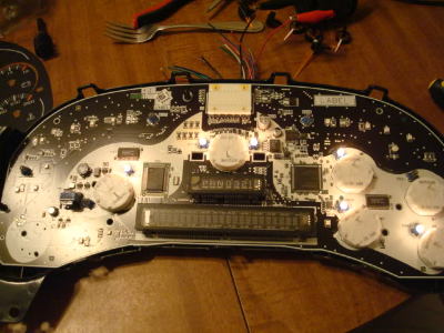
DSC02547.jpg

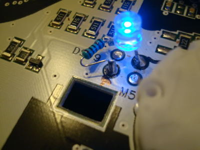
Now at this point, you should have all your polarity marked and the stock bulbs removed. Now you can solder your resistors to the LEDs. The resistor needs to go on the positive leg of the LED. Now carefully solder the resistor to the terminal that you marked positive, and the other leg of the LED to negative terminal.
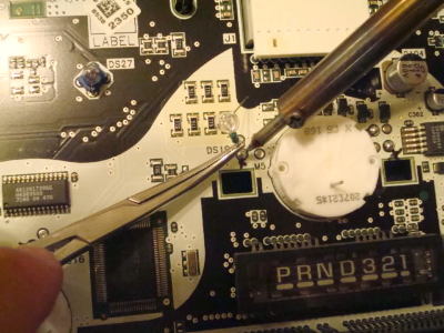
DSC02550.jpg
DSC02551.jpg

Now do the same thing across the board with 9 more LEDs. Now power up the cluster to verify all the LEDs are working, before you re-assmble everything.
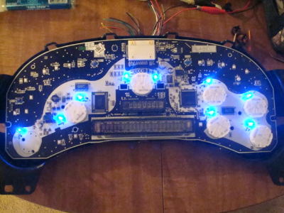
DSC02552.jpg

At this point you can lay the clear diffuser and the graphic overlay back on and see if any of the LEDs need to be moved or "adjusted" for better light output or spread.
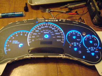
DSC02553.jpg

ScottyBoy - I'm following your steps on the Gauge Cluster LED replacement. You state "The resistor needs to go on the positive leg of the LED." Are you sure this is correct? If I recall my EE learnings correctly, the resistor goes on the negative side of the LED. Just want to ensure that I don't encounter any challenges once I reconnect the cluster. Thanks, man! Cheers.
 
OP
OP
S

ScottyBoy

Full Access Member
Joined
Jun 27, 2010
Posts
2,568
Reaction score
1,732
Location
Shreveport, La
ScottyBoy - I'm following your steps on the Gauge Cluster LED replacement. You state "The resistor needs to go on the positive leg of the LED." Are you sure this is correct? If I recall my EE learnings correctly, the resistor goes on the negative side of the LED. Just want to ensure that I don't encounter any challenges once I reconnect the cluster. Thanks, man! Cheers.
Actually, I have seen it done both ways, and it will work either way. Everything I read about states that you should put it online on the positive leg, but I have had people tell me to put it on the negative leg like you. I have actually tried it and it does work as long as you don't confuse the negative and positive leads and keep them wired properly.
 

05Single

afraid of the dark
Joined
Feb 26, 2015
Posts
8,183
Reaction score
11,447
View media item 25854
That's what I did. AC was done the same way and no problems at all.
Here's my original post.


http://www.tahoeyukonforum.com/threads/transmission-cooler-and-gauge.82149/page-2#post-1037070
Thats crazy! This is exactly what I've been throwing around in my head as an idea . First one I've seen done and it looks amazing.

Got any pics of how you did the a/c ?

Still wondering if you can get small enough strip cut down to fit behind the headlight switch. Door switches have to be individually soldered no matter what. Doubt strips would fit.

You said you soldered straight to the original lights on the dash. Just clipped the oem lights off then picked a light to solder to?
More info!!!:yuno:

I honestly would send mine off to @ScottyBoy again like i did with my silverado cluster but it's just so rediculous on shipping cost and wait time up here to Alaska.

He did my silverado lights and they were amazing. Worth every penny, I was also making tons of $$ back then lol. Best mod I ever did to that truck.
 

Forum statistics

Threads
129,117
Posts
1,810,709
Members
92,203
Latest member
firedog9518

Latest posts

Top